
Hardware Maintenance Manual
Page 5
...connectors on the rear of the computer . . 92 Removing the cover 92 Locating components 94 Identifying parts on the system board . . . . . 118 Removing and replacing memory 119 Removing and ... General Checkout . . . . . 45 Problem determination tips 46 Chapter 5. Replacing FRUs (Types 8095, 8141, 8142, 8145, 8420, and 8421) 91 Locating controls and connectors on the front of the computer 91...Password 56 Administrator Password 56 IDE Drive User Password 56 IDE Drive Master Password 56 © Lenovo 2005, 2008. hard drive 53 Viewing the test log 54 Chapter 6. Using the Setup Utility...
...connectors on the rear of the computer . . 92 Removing the cover 92 Locating components 94 Identifying parts on the system board . . . . . 118 Removing and replacing memory 119 Removing and ... General Checkout . . . . . 45 Problem determination tips 46 Chapter 5. Replacing FRUs (Types 8095, 8141, 8142, 8145, 8420, and 8421) 91 Locating controls and connectors on the front of the computer 91...Password 56 Administrator Password 56 IDE Drive User Password 56 IDE Drive Master Password 56 © Lenovo 2005, 2008. hard drive 53 Viewing the test log 54 Chapter 6. Using the Setup Utility...
Hardware Maintenance Manual
Page 6
FRU lists 161 Machine Type 8095 161 Machine Type 8098 167 Machine Type 8141 172 Machine Type 8142 187 Machine Type 8143 198 Machine Type 8144 214 Machine Type 8145 224 Machine Type 8146 231 Machine Type 8171 237 ... connectors on the front of the computer 137 Locating connectors on the rear of the computer 138 Opening the cover 138 Locating components 139 Identifying parts on the system board . . . . . 140 Removing and replacing memory 141 Replacing a PCI adapter 142 Removing and replacing the battery 143 Removing and replacing the power...
FRU lists 161 Machine Type 8095 161 Machine Type 8098 167 Machine Type 8141 172 Machine Type 8142 187 Machine Type 8143 198 Machine Type 8144 214 Machine Type 8145 224 Machine Type 8146 231 Machine Type 8171 237 ... connectors on the front of the computer 137 Locating connectors on the rear of the computer 138 Opening the cover 138 Locating components 139 Identifying parts on the system board . . . . . 140 Removing and replacing memory 141 Replacing a PCI adapter 142 Removing and replacing the battery 143 Removing and replacing the power...
Hardware Maintenance Manual
Page 101
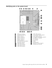
Identifying parts on the system board 1 12V power connector 2 Diskette drive connector 3 Speaker connector 4 Memory connector 4 5 Memory connector 3 6 Memory connector 2 7 Memory connector 1 8 Clear CMOS/Recovery jumper 9 Front ... x1 connector 19 PCI connector 20 PCI connector 21 Battery 22 Microprocessor 23 Microprocessor fan connector 24 Microprocessor heat sink Chapter 8. Replacing FRUs (Types 8095, 8141, 8142, 8145, 8420, and 8421) 95
Identifying parts on the system board 1 12V power connector 2 Diskette drive connector 3 Speaker connector 4 Memory connector 4 5 Memory connector 3 6 Memory connector 2 7 Memory connector 1 8 Clear CMOS/Recovery jumper 9 Front ... x1 connector 19 PCI connector 20 PCI connector 21 Battery 22 Microprocessor 23 Microprocessor fan connector 24 Microprocessor heat sink Chapter 8. Replacing FRUs (Types 8095, 8141, 8142, 8145, 8420, and 8421) 95
Hardware Maintenance Manual
Page 105
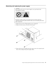
...label attached. Note of the routing of the chassis. 3. Chapter 8. Hazardous voltage, current, and energy levels are no servicable parts inside any part that has this label attached. Remove the cover. There are present inside these components. 1. Remove the four screws at the rear... of the power supply cables. Removing and replacing the power supply Attention Never remove the cover on page 92. 2. Replacing FRUs (Types 8095, 8141...
...label attached. Note of the routing of the chassis. 3. Chapter 8. Hazardous voltage, current, and energy levels are no servicable parts inside any part that has this label attached. Remove the cover. There are present inside these components. 1. Remove the four screws at the rear... of the power supply cables. Removing and replacing the power supply Attention Never remove the cover on page 92. 2. Replacing FRUs (Types 8095, 8141...

Hardware Maintenance Manual
Page 107
...replacing the system board 1. See "Removing and replacing a PCI adapter" on page 92. 2. See "Identifying parts on the system board" on the system board. Carefully note the location of the chassis. 9. Remove the cover.... Remove any PCI adapters. Replacing FRUs (Types 8095, 8141, 8142, 8145, 8420, and 8421) 101 Install and tighten the four power supply assembly screws ...a new system board. 4. Note: Use only the screws provided by Lenovo. 8. Install the new power supply assembly into the rear of all cables connected to the system board. ...
...replacing the system board 1. See "Removing and replacing a PCI adapter" on page 92. 2. See "Identifying parts on the system board" on the system board. Carefully note the location of the chassis. 9. Remove the cover.... Remove any PCI adapters. Replacing FRUs (Types 8095, 8141, 8142, 8145, 8420, and 8421) 101 Install and tighten the four power supply assembly screws ...a new system board. 4. Note: Use only the screws provided by Lenovo. 8. Install the new power supply assembly into the rear of all cables connected to the system board. ...
Hardware Maintenance Manual
Page 109
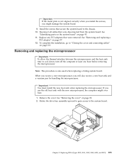
If you will also receive a new heat sink and a vacuum pen for handling the microprocessor. Replacing FRUs (Types 8095, 8141, 8142, 8145, 8420, and 8421) 103 See "Identifying parts on the system board" on page 92. 2. Removing and replacing the microprocessor Important To allow the thermal interface between the microprocessor and the heat...
If you will also receive a new heat sink and a vacuum pen for handling the microprocessor. Replacing FRUs (Types 8095, 8141, 8142, 8145, 8420, and 8421) 103 See "Identifying parts on the system board" on page 92. 2. Removing and replacing the microprocessor Important To allow the thermal interface between the microprocessor and the heat...
Hardware Maintenance Manual
Page 119
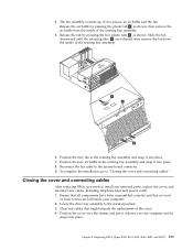
... over the computer until the retaining tabs 2 are left inside of the cover. 4. Replacing FRUs (Types 8095, 8141, 8142, 8145, 8420, and 8421) 113 To complete the installation, go to install any removed parts, replace the cover, and reconnect any cables that no tools or loose screws are released, then remove the...
... over the computer until the retaining tabs 2 are left inside of the cover. 4. Replacing FRUs (Types 8095, 8141, 8142, 8145, 8420, and 8421) 113 To complete the installation, go to install any removed parts, replace the cover, and reconnect any cables that no tools or loose screws are released, then remove the...


