User Guide
Page 4
... items as defined by 48 C.F.R. 2.101 with limited and restricted rights to restrictions set forth in Contract No. All rights reserved. LENOVO products, data, computer software, and services have been developed exclusively at private expense and are delivered pursuant a General Services Administration ″... is subject to use, reproduction and disclosure. Second Edition (May 2009) © Copyright Lenovo 2009. Note Before using this information and the product it supports, be sure to read and understand the ThinkCentre Safety and Warranty Guide and "Notices," on page 65. GS-35F-05925.
... items as defined by 48 C.F.R. 2.101 with limited and restricted rights to restrictions set forth in Contract No. All rights reserved. LENOVO products, data, computer software, and services have been developed exclusively at private expense and are delivered pursuant a General Services Administration ″... is subject to use, reproduction and disclosure. Second Edition (May 2009) © Copyright Lenovo 2009. Note Before using this information and the product it supports, be sure to read and understand the ThinkCentre Safety and Warranty Guide and "Notices," on page 65. GS-35F-05925.
User Guide
Page 5
...from the Setup Utility program . . . . . 50 Chapter 5. Notices 65 Television output notice 66 Trademarks 66 Index 67 © Copyright Lenovo 2009 iii Using the Setup Utility . . . 47 Starting the Setup Utility program 47 Viewing and changing settings 47 Using passwords 47 Password ...50 Exiting from a POST/BIOS update failure . . . 52 Chapter 6. Troubleshooting and diagnostics 55 Basic troubleshooting 55 Diagnostic programs 57 Lenovo System Toolbox 57 PC-Doctor for Windows PE 57 PC-Doctor for service 63 Using other services 64 Purchasing additional services 64 Appendix....
...from the Setup Utility program . . . . . 50 Chapter 5. Notices 65 Television output notice 66 Trademarks 66 Index 67 © Copyright Lenovo 2009 iii Using the Setup Utility . . . 47 Starting the Setup Utility program 47 Viewing and changing settings 47 Using passwords 47 Password ...50 Exiting from a POST/BIOS update failure . . . 52 Chapter 6. Troubleshooting and diagnostics 55 Basic troubleshooting 55 Diagnostic programs 57 Lenovo System Toolbox 57 PC-Doctor for Windows PE 57 PC-Doctor for service 63 Using other services 64 Purchasing additional services 64 Appendix....
User Guide
Page 7
Refer to the ThinkCentre Safety and Warranty Guide that you can obtain a Portable Document Format (PDF) version from the Lenovo® Support Web site at: http://www.lenovo.com/support © Copyright Lenovo 2009 v Important safety information CAUTION: Before using this manual, be sure to read ...and understand all the related safety information for the latest safety information. If you no longer have a copy of the ThinkCentre Safety and Warranty ...
Refer to the ThinkCentre Safety and Warranty Guide that you can obtain a Portable Document Format (PDF) version from the Lenovo® Support Web site at: http://www.lenovo.com/support © Copyright Lenovo 2009 v Important safety information CAUTION: Before using this manual, be sure to read ...and understand all the related safety information for the latest safety information. If you no longer have a copy of the ThinkCentre Safety and Warranty ...
User Guide
Page 9
... specific model, use these instructions along with the instructions that are available for discrete graphics card © Copyright Lenovo 2009 1 See Chapter 4, "Using the Setup Utility," on the system board for your computer by Lenovo. You can expand the capabilities of your computer. Chapter 1. When installing or replacing an option, use the...
... specific model, use these instructions along with the instructions that are available for discrete graphics card © Copyright Lenovo 2009 1 See Chapter 4, "Using the Setup Utility," on the system board for your computer by Lenovo. You can expand the capabilities of your computer. Chapter 1. When installing or replacing an option, use the...
User Guide
Page 10
Audio subsystem v Audio line-in connector, audio line-out connector, and microphone connector on the rear panel v High Definition (HD) with ADI 1882 Audio Codec v Microphone connector and headphone connector on the front panel v Mono internal speaker (some models) Connectivity v 10/100/1000 Mbps integrated Ethernet controller v PCI V.90 Data/Fax modem (some models) System management features v Ability to store power-on self-test (POST) hardware test results v Automatic power-on startup v ASF 2.0 (Alert Standard Format) v Intel Active Management Technology (AMT) (some models) v Intel matrix ...
Audio subsystem v Audio line-in connector, audio line-out connector, and microphone connector on the rear panel v High Definition (HD) with ADI 1882 Audio Codec v Microphone connector and headphone connector on the front panel v Mono internal speaker (some models) Connectivity v 10/100/1000 Mbps integrated Ethernet controller v PCI V.90 Data/Fax modem (some models) System management features v Ability to store power-on self-test (POST) hardware test results v Automatic power-on startup v ASF 2.0 (Alert Standard Format) v Intel Active Management Technology (AMT) (some models) v Intel matrix ...
User Guide
Page 11
... features, and other support programs are subject to this booklet. To determine if an operating system has been certified or tested for compatibility1 (varies by Lenovo as compatible with your computer following the publication of this list are included. Operating systems, certified or tested for compatibility, check the Web site of...
... features, and other support programs are subject to this booklet. To determine if an operating system has been certified or tested for compatibility1 (varies by Lenovo as compatible with your computer following the publication of this list are included. Operating systems, certified or tested for compatibility, check the Web site of...
User Guide
Page 12
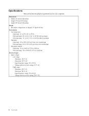
Specifications This section lists the physical specifications for your computer. Dimensions Width: 317 mm (12.48 inches) Height: 99 mm (3.90 inches) Depth: 355 mm (13.98 inches) Weight Maximum configuration as shipped: 7.5 kg (16.53 lbs) Environment Air temperature: Operating: 10° to 35°C (50° to 95°F) Non-operating: -40° to 60°C (-40° to 140°F) (with package) Non-operating: -10° to 60°C (14° to 140°F) (without package) Humidity: Operating: 10% to 80% (10% per hour, non condensing) Non-operating: 10% to 90% (10% per hour, non ...
Specifications This section lists the physical specifications for your computer. Dimensions Width: 317 mm (12.48 inches) Height: 99 mm (3.90 inches) Depth: 355 mm (13.98 inches) Weight Maximum configuration as shipped: 7.5 kg (16.53 lbs) Environment Air temperature: Operating: 10° to 35°C (50° to 95°F) Non-operating: -40° to 60°C (-40° to 140°F) (with package) Non-operating: -10° to 60°C (14° to 140°F) (without package) Humidity: Operating: 10% to 80% (10% per hour, non condensing) Non-operating: 10% to 90% (10% per hour, non ...
User Guide
Page 13
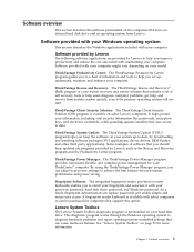
...ThinkVantage Power Manager: The ThinkVantage Power Manager program provides convenient, flexible, and complete power management for more information. See "Lenovo System Toolbox" on page 57 for your system up , understand, maintain, and enhance your computer. Product overview 5 ThinkVantage... help , and recover from Lenovo. By using the ThinkVantage Power Manager program, you set of software that you should keep the software on select Lenovo computers. Lenovo System Toolbox The Lenovo System Toolbox diagnostic program is available on your ThinkCentre® computer.
...ThinkVantage Power Manager: The ThinkVantage Power Manager program provides convenient, flexible, and complete power management for more information. See "Lenovo System Toolbox" on page 57 for your system up , understand, maintain, and enhance your computer. Product overview 5 ThinkVantage... help , and recover from Lenovo. By using the ThinkVantage Power Manager program, you set of software that you should keep the software on select Lenovo computers. Lenovo System Toolbox The Lenovo System Toolbox diagnostic program is available on your ThinkCentre® computer.
User Guide
Page 14
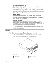
... you can cause hardware failures. Adobe Reader The Adobe Reader is part of the Rescue and Recovery workspace on each Lenovo computer to start the Windows operating system or if the Lenovo System Toolbox has not been successful in isolating a possible problem. It is a tool used to the Access Help...view, print, and search PDF documents. PC-Doctor for Windows PE The PC-Doctor for Windows PE diagnostic program is preinstalled on your computer. Lenovo provides a full version of your hard disk drive. Use the PC-Doctor for Windows PE if you must renew the license to open the online...
... you can cause hardware failures. Adobe Reader The Adobe Reader is part of the Rescue and Recovery workspace on each Lenovo computer to start the Windows operating system or if the Lenovo System Toolbox has not been successful in isolating a possible problem. It is a tool used to the Access Help...view, print, and search PDF documents. PC-Doctor for Windows PE The PC-Doctor for Windows PE diagnostic program is preinstalled on your computer. Lenovo provides a full version of your hard disk drive. Use the PC-Doctor for Windows PE if you must renew the license to open the online...
User Guide
Page 15
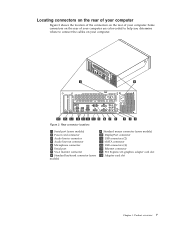
Some connectors on your computer. Figure 2. Rear connector locations 1 Serial port (some models) 2 Power cord connector 3 Audio line-in connector 4 Audio line-out connector 5 Microphone connector 6 Serial port 7 VGA monitor connector 8 Standard keyboard connector (some models) 9 Standard mouse connector (some models) 10 DisplayPort connector 11 USB connectors (2) 12 eSATA connector 13 USB connectors (4) 14 Ethernet connector 15 PCI Express x16 graphics adapter card slot 16 Adapter card slot Chapter 1. Product overview 7 Locating connectors on the rear of your computer Figure 2 ...
Some connectors on your computer. Figure 2. Rear connector locations 1 Serial port (some models) 2 Power cord connector 3 Audio line-in connector 4 Audio line-out connector 5 Microphone connector 6 Serial port 7 VGA monitor connector 8 Standard keyboard connector (some models) 9 Standard mouse connector (some models) 10 DisplayPort connector 11 USB connectors (2) 12 eSATA connector 13 USB connectors (4) 14 Ethernet connector 15 PCI Express x16 graphics adapter card slot 16 Adapter card slot Chapter 1. Product overview 7 Locating connectors on the rear of your computer Figure 2 ...
User Guide
Page 16
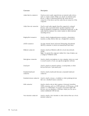
Audio line-out connector Used to send audio signals from an external audio device, such as a stereo system. DisplayPort connector Used to external devices, such as a USB keyboard, a USB mouse, a USB scanner or a USB printer. Note: To operate the computer within FCC Class B limits, use a Category 5 Ethernet cable. Ethernet connector Used to attach a device that use a DisplayPort connector. USB connector Used to attach an Ethernet cable for a local area network (LAN). If you have more than eight USB devices, you can purchase a USB hub, which you can use to attach...
Audio line-out connector Used to send audio signals from an external audio device, such as a stereo system. DisplayPort connector Used to external devices, such as a USB keyboard, a USB mouse, a USB scanner or a USB printer. Note: To operate the computer within FCC Class B limits, use a Category 5 Ethernet cable. Ethernet connector Used to attach a device that use a DisplayPort connector. USB connector Used to attach an Ethernet cable for a local area network (LAN). If you have more than eight USB devices, you can purchase a USB hub, which you can use to attach...
User Guide
Page 17
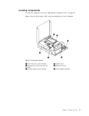
Figure 3. Product overview 9 Component locations 1 Hard disk drive (some models) 2 Microprocessor, heat sink and fan assembly 3 Internal speaker (some models) 4 Optical drive 5 Memory slots (4) 6 Power supply assembly Chapter 1. Figure 3 shows the location of the various components in your computer. Locating components To open the computer cover, see "Opening the computer cover" on page 12.
Figure 3. Product overview 9 Component locations 1 Hard disk drive (some models) 2 Microprocessor, heat sink and fan assembly 3 Internal speaker (some models) 4 Optical drive 5 Memory slots (4) 6 Power supply assembly Chapter 1. Figure 3 shows the location of the various components in your computer. Locating components To open the computer cover, see "Opening the computer cover" on page 12.

User Guide
Page 18
Locating parts on the system board Figure 4 shows the location of the parts on the system board. Figure 4. System board parts locations 1 PCI adapter card slot 2 PCI Express x16 graphics adapter card slot 3 Battery 4 Internal speaker connector 5 Cover presence switch (also called Intrusion switch) connector 6 Microprocessor fan connector 7 Thermal sensor connector 8 Microprocessor 9 4-pin power connector 10 Front panel connector 11 Memory slots (4) 12 24-pin power connector 13 Serial (COM 2) connector 14 Front audio connector 15 SATA connectors (2) 16 System fan connector 17 Front USB ...
Locating parts on the system board Figure 4 shows the location of the parts on the system board. Figure 4. System board parts locations 1 PCI adapter card slot 2 PCI Express x16 graphics adapter card slot 3 Battery 4 Internal speaker connector 5 Cover presence switch (also called Intrusion switch) connector 6 Microprocessor fan connector 7 Thermal sensor connector 8 Microprocessor 9 4-pin power connector 10 Front panel connector 11 Memory slots (4) 12 24-pin power connector 13 Serial (COM 2) connector 14 Front audio connector 15 SATA connectors (2) 16 System fan connector 17 Front USB ...
User Guide
Page 19
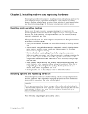
...computer. Static electricity, although harmless to you are ready to : http://www.lenovo.com/support Note: Use only computer parts provided by the edges. Movement can expand the capabilities of the ThinkCentre Safety and Warranty Guide, go to install the new part. Handle adapter cards..., memory modules, system boards, and microprocessors by Lenovo. © Copyright Lenovo 2009 11 Attention Do not open the static-protective package...
...computer. Static electricity, although harmless to you are ready to : http://www.lenovo.com/support Note: Use only computer parts provided by the edges. Movement can expand the capabilities of the ThinkCentre Safety and Warranty Guide, go to install the new part. Handle adapter cards..., memory modules, system boards, and microprocessors by Lenovo. © Copyright Lenovo 2009 11 Attention Do not open the static-protective package...
User Guide
Page 20
To open the computer cover. Remove any locking devices, such as a cable lock that are required for the option. For some external options, you make the connection and install any other cables that secures the computer cover. 12 User Guide Disconnect the cables attached to making the physical connection. See "Locating connectors on the front of your computer" on page 6 and "Locating connectors on the rear of your computer" on page 7. 4. Unplug all attached devices and the computer. 2. Remove any media from electrical outlets. 3. CAUTION: The heat sink and ...
To open the computer cover. Remove any locking devices, such as a cable lock that are required for the option. For some external options, you make the connection and install any other cables that secures the computer cover. 12 User Guide Disconnect the cables attached to making the physical connection. See "Locating connectors on the front of your computer" on page 6 and "Locating connectors on the rear of your computer" on page 7. 4. Unplug all attached devices and the computer. 2. Remove any media from electrical outlets. 3. CAUTION: The heat sink and ...

User Guide
Page 21
Opening the computer cover Chapter 2. Press the buttons on the sides of the computer and pivot the computer cover upward to open. Installing options and replacing hardware 13 5. Figure 5.
Opening the computer cover Chapter 2. Press the buttons on the sides of the computer and pivot the computer cover upward to open. Installing options and replacing hardware 13 5. Figure 5.
User Guide
Page 22
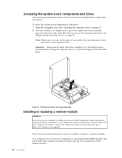
...: Make sure the hard disk drive assembly is in the latched down position before reading and understanding the "Important safety information" in the ThinkCentre Safety and Warranty Guide that provide up to a maximum of 8 GB system memory. Your computer has four slots for installing or replacing ... instructions on how to install or replace a memory module. On some models, you note the location of the ThinkCentre Safety and Warranty Guide, go to: http://www.lenovo.com/support 14 User Guide This section provides instructions on how to access the internal components. Note: Make sure...
...: Make sure the hard disk drive assembly is in the latched down position before reading and understanding the "Important safety information" in the ThinkCentre Safety and Warranty Guide that provide up to a maximum of 8 GB system memory. Your computer has four slots for installing or replacing ... instructions on how to install or replace a memory module. On some models, you note the location of the ThinkCentre Safety and Warranty Guide, go to: http://www.lenovo.com/support 14 User Guide This section provides instructions on how to access the internal components. Note: Make sure...
User Guide
Page 23
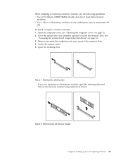
Open the computer cover. Opening the retaining clips If you are replacing an old memory module, open the retaining clips and remove the memory module being replaced as shown. See "Accessing the system board components and drives" on page 12. 2. Figure 7. See "Opening the computer cover" on page 14. 3. Remove any combination up to a maximum of 8 GB. Locate the memory slots. 5. Figure 8. Installing options and replacing hardware 15 Removing the old memory module Chapter 2. When installing or replacing a memory module, use the following guidelines: v Use 1.8 V, 240-pin, DDR3 ...
Open the computer cover. Opening the retaining clips If you are replacing an old memory module, open the retaining clips and remove the memory module being replaced as shown. See "Accessing the system board components and drives" on page 12. 2. Figure 7. See "Opening the computer cover" on page 14. 3. Remove any combination up to a maximum of 8 GB. Locate the memory slots. 5. Figure 8. Installing options and replacing hardware 15 Removing the old memory module Chapter 2. When installing or replacing a memory module, use the following guidelines: v Use 1.8 V, 240-pin, DDR3 ...

User Guide
Page 24
... an adapter card Attention Do not open your computer or attempt any repair before reading and understanding the "Important safety information" in the ThinkCentre Safety and Warranty Guide that the notch 1 on the memory module aligns correctly with your computer. v To complete the installation, go...the retaining clips close. Make sure that came with the slot key 2 on page 35. To obtain a copy of the ThinkCentre Safety and Warranty Guide, go to: http://www.lenovo.com/support This section provides instructions on how to "Completing the parts replacement" on the system board. 6.
... an adapter card Attention Do not open your computer or attempt any repair before reading and understanding the "Important safety information" in the ThinkCentre Safety and Warranty Guide that the notch 1 on the memory module aligns correctly with your computer. v To complete the installation, go...the retaining clips close. Make sure that came with the slot key 2 on page 35. To obtain a copy of the ThinkCentre Safety and Warranty Guide, go to: http://www.lenovo.com/support This section provides instructions on how to "Completing the parts replacement" on the system board. 6.
User Guide
Page 25
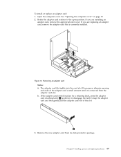
See "Opening the computer cover" on page 12. 2. If you are replacing an adapter card, remove the adapter card that is currently installed. Open the computer cover. Rotate the adapter card retainer to disengage the latch. b. Remove the new adapter card from the adapter card slot. The adapter card fits tightly into the card slot. If necessary, alternate moving each side of the slot. 3. Chapter 2. If you are installing an adapter card, remove the appropriate slot cover. If the adapter card is removed from its static-protective package. Installing options and replacing ...
See "Opening the computer cover" on page 12. 2. If you are replacing an adapter card, remove the adapter card that is currently installed. Open the computer cover. Rotate the adapter card retainer to disengage the latch. b. Remove the new adapter card from the adapter card slot. The adapter card fits tightly into the card slot. If necessary, alternate moving each side of the slot. 3. Chapter 2. If you are installing an adapter card, remove the appropriate slot cover. If the adapter card is removed from its static-protective package. Installing options and replacing ...
