Owner's Manual
Page 2
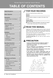
...locate the nearest ASC. • This air conditioner is not intended for service at all. Window-Type Air Conditioner Owner's Manual TABLE OF CONTENTS Safety Precautions 3 Before Operation 7 Introduction 8 Symbols Used in this Manual ........8 Features 8 Electrical Safety 9 Temporary Use of an Adapter 11 Temporary...Control Operations ........18 Remote Controller 19 Additional Features 20 Air Direction 20 Drain Pipe 20 Removal from Window 20 Maintenance and Service 21 Air Filter 21 Cleaning the Air Conditioner .....21 How to use by qualified and authorized personnel only. 2 Room...
...locate the nearest ASC. • This air conditioner is not intended for service at all. Window-Type Air Conditioner Owner's Manual TABLE OF CONTENTS Safety Precautions 3 Before Operation 7 Introduction 8 Symbols Used in this Manual ........8 Features 8 Electrical Safety 9 Temporary Use of an Adapter 11 Temporary...Control Operations ........18 Remote Controller 19 Additional Features 20 Air Direction 20 Drain Pipe 20 Removal from Window 20 Maintenance and Service 21 Air Filter 21 Cleaning the Air Conditioner .....21 How to use by qualified and authorized personnel only. 2 Room...
Owner's Manual
Page 7
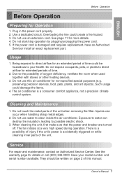
... time could be written on while cleaning inner parts of injury if the unit's power is damaged and requires replacement, have an Authorized Servicer install an exact replacement part. preserving precision devices, food, pets, plants, and art objects). Do not touch the metal parts of ...time. 2. Exposure to possible electric shock. 3. Owner's Manual 7 Do not use this manual. Do not start/stop operation by plugging/unplugging the power cord. 5. Do not use an extension cord. Injuries can destroy the insulation...
... time could be written on while cleaning inner parts of injury if the unit's power is damaged and requires replacement, have an Authorized Servicer install an exact replacement part. preserving precision devices, food, pets, plants, and art objects). Do not touch the metal parts of ...time. 2. Exposure to possible electric shock. 3. Owner's Manual 7 Do not use this manual. Do not start/stop operation by plugging/unplugging the power cord. 5. Do not use an extension cord. Injuries can destroy the insulation...
Owner's Manual
Page 21
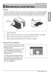
...the airflow, reducing cooling capacity and causing an accumulation of unit) should be wiped with soot or dirt from the atmosphere. Owner's Manual 21 Lift the inlet grille. 2. Cleaning The Air Conditioner The front grille and Inlet grille may be washed with mild soap or ...water, then polished with Liquid Wax for Appliances. Wash the filter using lukewarm water below 40 °C (104 °F). 4. Maintenance and Service Maintenance and Service Air Filter Check the air filter at least twice a month to far. 1. To ensure continued peak efficiency, the condenser coils (outside of...
...the airflow, reducing cooling capacity and causing an accumulation of unit) should be wiped with soot or dirt from the atmosphere. Owner's Manual 21 Lift the inlet grille. 2. Cleaning The Air Conditioner The front grille and Inlet grille may be washed with mild soap or ...water, then polished with Liquid Wax for Appliances. Wash the filter using lukewarm water below 40 °C (104 °F). 4. Maintenance and Service Maintenance and Service Air Filter Check the air filter at least twice a month to far. 1. To ensure continued peak efficiency, the condenser coils (outside of...
Service Manual
Page 1
website http://www.lgappliances.com LG LG Room Air Conditioner SERVICE MANUAL MODELS: LWHD8008R CAUTION • BEFORE SERVICING THE UNIT, READ THE SAFETY PRECAUTIONS IN THIS MANUAL. • ONLY FOR AUTHORIZED SERVICE PERSONNEL.
website http://www.lgappliances.com LG LG Room Air Conditioner SERVICE MANUAL MODELS: LWHD8008R CAUTION • BEFORE SERVICING THE UNIT, READ THE SAFETY PRECAUTIONS IN THIS MANUAL. • ONLY FOR AUTHORIZED SERVICE PERSONNEL.
Service Manual
Page 3
... system. The refrigerant is charged at the factory. PREFACE This service manual provides various service information, including the mechanical and electrical parts, etc. Be sure to read the safety precautions prior to servicing the unit. 1.1 FEATURES • DESIGNED FOR COOLING ONLY •...; POWERFUL AND INCREDIBLE COOLING • TOP-DOWN CHASSIS FOR THE SIMPLE INSTALLATION AND SERVICE • BUILT-IN ADJUSTABLE THERMOSTAT • WASHABLE ONE-TOUCH FILTER • COMPACT SIZE 1.2 SPECIFICATIONS ITEMS MODELS COOLING CAPACITY ...
... system. The refrigerant is charged at the factory. PREFACE This service manual provides various service information, including the mechanical and electrical parts, etc. Be sure to read the safety precautions prior to servicing the unit. 1.1 FEATURES • DESIGNED FOR COOLING ONLY •...; POWERFUL AND INCREDIBLE COOLING • TOP-DOWN CHASSIS FOR THE SIMPLE INSTALLATION AND SERVICE • BUILT-IN ADJUSTABLE THERMOSTAT • WASHABLE ONE-TOUCH FILTER • COMPACT SIZE 1.2 SPECIFICATIONS ITEMS MODELS COOLING CAPACITY ...
Service Manual
Page 4
... unit. 1.1 FEATURES • DESIGNED FOR COOLING ONLY • POWERFUL AND INCREDIBLE COOLING • TOP-DOWN CHASSIS FOR THE SIMPLE INSTALLATION AND SERVICE • BUILT-IN ADJUSTABLE THERMOSTAT • WASHABLE ONE-TOUCH FILTER • COMPACT SIZE 1.2 SPECIFICATIONS ITEMS MODELS COOLING CAPACITY (BTU/h) POWER SUPPLY (Phase...HIGH COOL, LOW COOL) 6 POLES, 16W -3- 1-1. This room air conditioner was manufactured and assembled under a strict quality control system. PREFACE This service manual provides various service information, including the mechanical and electrical parts, etc.
... unit. 1.1 FEATURES • DESIGNED FOR COOLING ONLY • POWERFUL AND INCREDIBLE COOLING • TOP-DOWN CHASSIS FOR THE SIMPLE INSTALLATION AND SERVICE • BUILT-IN ADJUSTABLE THERMOSTAT • WASHABLE ONE-TOUCH FILTER • COMPACT SIZE 1.2 SPECIFICATIONS ITEMS MODELS COOLING CAPACITY (BTU/h) POWER SUPPLY (Phase...HIGH COOL, LOW COOL) 6 POLES, 16W -3- 1-1. This room air conditioner was manufactured and assembled under a strict quality control system. PREFACE This service manual provides various service information, including the mechanical and electrical parts, etc.

Service Manual
Page 6
..., wires, and capacitor are now accessible for the fan motor and compressor. (See Figure 5) 7. Disconnect one housing terminal and 3 wires for servicing. Pull the top of the front grille away from source of their slots. (See Figure 2) 4. Remove the front grille. (Refer to Section... 2.1.1) 3. Pull the control board toward yourself. Re-install components by placing the tabs in this manual or inside control board.) Figure 3 Figure 4 Figure 5 -5- Re-install by pulling them off. Remove the front grille. (Refer to section 2.1.1) ...
..., wires, and capacitor are now accessible for the fan motor and compressor. (See Figure 5) 7. Disconnect one housing terminal and 3 wires for servicing. Pull the top of the front grille away from source of their slots. (See Figure 2) 4. Remove the front grille. (Refer to Section... 2.1.1) 3. Pull the control board toward yourself. Re-install components by placing the tabs in this manual or inside control board.) Figure 3 Figure 4 Figure 5 -5- Re-install by pulling them off. Remove the front grille. (Refer to section 2.1.1) ...


