Owner's Manual
Page 2
... with the air conditioner. • If the power cord requires replacement, have an Authorized Servicer install an exact replacement part. • Installation work must be supervised to use and maintain your part can save you will find many answers to Remove the Front Grille 22 Common Problems and Solutions 23 Troubleshooting 24...
... with the air conditioner. • If the power cord requires replacement, have an Authorized Servicer install an exact replacement part. • Installation work must be supervised to use and maintain your part can save you will find many answers to Remove the Front Grille 22 Common Problems and Solutions 23 Troubleshooting 24...
Owner's Manual
Page 5
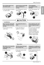
... the inlet or outlet. • It may cause injury. Leaving it will cause failure of appliance or accident. ENGLISH • Installation Never touch the metal parts of the unit when removing the filter. • They are sharp and may cause failure of machine • It is running. Leave the door closed... while the air conditioner is not designed to run into electric parts. Do not operate the air conditioner if you smell gas. • It will not be repaired or replaced immediately.
... the inlet or outlet. • It may cause injury. Leaving it will cause failure of appliance or accident. ENGLISH • Installation Never touch the metal parts of the unit when removing the filter. • They are sharp and may cause failure of machine • It is running. Leave the door closed... while the air conditioner is not designed to run into electric parts. Do not operate the air conditioner if you smell gas. • It will not be repaired or replaced immediately.
Owner's Manual
Page 7
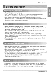
... plugging/unplugging the power cord. 5. The air conditioner is damaged and requires replacement, have an Authorized Servicer install an exact replacement part. Injuries can destroy the insulation, leading to direct airflow for non-specified special purposes (e.g. They should be hazardous to direct airflow for... See the warranty page for Operation 1. preserving precision devices, food, pets, plants, and art objects). Do not touch the metal parts of oxygen deficiency, ventilate the room when used together with stoves or other heating devices. 3. Service For repair and maintenance, contact ...
... plugging/unplugging the power cord. 5. The air conditioner is damaged and requires replacement, have an Authorized Servicer install an exact replacement part. Injuries can destroy the insulation, leading to direct airflow for non-specified special purposes (e.g. They should be hazardous to direct airflow for... See the warranty page for Operation 1. preserving precision devices, food, pets, plants, and art objects). Do not touch the metal parts of oxygen deficiency, ventilate the room when used together with stoves or other heating devices. 3. Service For repair and maintenance, contact ...
Service Manual
Page 2
... ...6 2.2.1 AIR GUIDE UPPER ...6 2.2.2 ORIFICE, TURBO FAN AND FAN ...6 2.2.3 MOTOR ...7 2.2.4 AIR GUIDE ...7 2.3 ELECTRICAL PARTS ...7 2.3.1 OVERLOAD PROTECTOR ...7 2.3.2 COMPRESSOR ...8 2.3.3 CAPACITOR ...8 2.3.4 THERMOSTAT ...8 2.3.5 ROTARY SWITCH ...8 2.3.6 POWER CORD ...9 2.4 REFRIGERANT CYCLE ...9 2.4.1 CONDENSER ...9 2.4.2 EVAPORATOR ...10 2.4.3 CAPILLARY TUBE ...10 3. PREFACE ...3 1.1 FEATURES...3 1.2 SPECIFICATIONS ...3 1.3 LOCATIONS OF CONTROLS ...4 1.4 SAFETY PRECAUTIONS ...4 1.5 ...
... ...6 2.2.1 AIR GUIDE UPPER ...6 2.2.2 ORIFICE, TURBO FAN AND FAN ...6 2.2.3 MOTOR ...7 2.2.4 AIR GUIDE ...7 2.3 ELECTRICAL PARTS ...7 2.3.1 OVERLOAD PROTECTOR ...7 2.3.2 COMPRESSOR ...8 2.3.3 CAPACITOR ...8 2.3.4 THERMOSTAT ...8 2.3.5 ROTARY SWITCH ...8 2.3.6 POWER CORD ...9 2.4 REFRIGERANT CYCLE ...9 2.4.1 CONDENSER ...9 2.4.2 EVAPORATOR ...10 2.4.3 CAPILLARY TUBE ...10 3. PREFACE ...3 1.1 FEATURES...3 1.2 SPECIFICATIONS ...3 1.3 LOCATIONS OF CONTROLS ...4 1.4 SAFETY PRECAUTIONS ...4 1.5 ...
Service Manual
Page 3
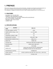
... 5 STEP (LOW FAN, HIGH FAN, OFF, HIGH COOL, LOW COOL) 6 POLES, 16W -3- 1. PREFACE This service manual provides various service information, including the mechanical and electrical parts, etc. This room air conditioner was manufactured and assembled under a strict quality control system. The refrigerant is charged at the factory.
... 5 STEP (LOW FAN, HIGH FAN, OFF, HIGH COOL, LOW COOL) 6 POLES, 16W -3- 1. PREFACE This service manual provides various service information, including the mechanical and electrical parts, etc. This room air conditioner was manufactured and assembled under a strict quality control system. The refrigerant is charged at the factory.
Service Manual
Page 4
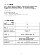
... 5 STEP (LOW FAN, HIGH FAN, OFF, HIGH COOL, LOW COOL) 6 POLES, 16W -3- PREFACE This service manual provides various service information, including the mechanical and electrical parts, etc. 1-1. The refrigerant is charged at the factory.
... 5 STEP (LOW FAN, HIGH FAN, OFF, HIGH COOL, LOW COOL) 6 POLES, 16W -3- PREFACE This service manual provides various service information, including the mechanical and electrical parts, etc. 1-1. The refrigerant is charged at the factory.
Service Manual
Page 5
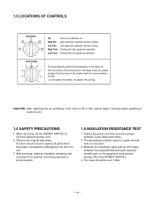
...3 7 2 1 8 9 This automatically controls the temperature of the ROTARY SWITCH. 4. When servicing, set the ROTARY SWITCH to Off or Fan, wait at all parts which have been overheated or damaged by the short circuit. 3. Unplug the power cord and connect a jumper between the jumpered lead and each exposed metallic... part on the equipment at least 3 minutes before switching it back to shock hazards. 1.5 INSULATION RESISTANCE TEST 1. The value should be open...
...3 7 2 1 8 9 This automatically controls the temperature of the ROTARY SWITCH. 4. When servicing, set the ROTARY SWITCH to Off or Fan, wait at all parts which have been overheated or damaged by the short circuit. 3. Unplug the power cord and connect a jumper between the jumpered lead and each exposed metallic... part on the equipment at least 3 minutes before switching it back to shock hazards. 1.5 INSULATION RESISTANCE TEST 1. The value should be open...

Service Manual
Page 6
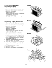
... snaps into place. Remove the front grille. (Refer to the base pan and condenser. (See Figure 3) 4. Disconnect the unit from the unit. 5. DISASSEMBLY INSTRUCTIONS 2.1 MECHANICAL PARTS 2.1.1 FRONT GRILLE 1. Replace the grille by pulling them off.
... snaps into place. Remove the front grille. (Refer to the base pan and condenser. (See Figure 3) 4. Disconnect the unit from the unit. 5. DISASSEMBLY INSTRUCTIONS 2.1 MECHANICAL PARTS 2.1.1 FRONT GRILLE 1. Replace the grille by pulling them off.
Service Manual
Page 7
... remove it from the power source. 2. Remove the cabinet. (Refer to Section 2.1.2) 4. Remove the clamp springs which are clamped to the procedures above . 2.2 AIR HANDLING PARTS 2.2.1 AIR GUIDE UPPER 1.
... remove it from the power source. 2. Remove the cabinet. (Refer to Section 2.1.2) 4. Remove the clamp springs which are clamped to the procedures above . 2.2 AIR HANDLING PARTS 2.2.1 AIR GUIDE UPPER 1.
Service Manual
Page 8
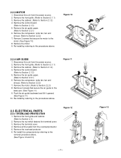
... the cabinet. (Refer to Section 2.2.2) 7. Remove the compressor, turbo fan, fan and shroud. (Refer to Section 2.2.3) 8. Remove the motor. (Refer to Section 2.2.2) 7. Figure 11 2.3 ELECTRICAL PARTS 2.3.1 OVERLOAD PROTECTOR 1. Remove the terminal cover. 4. Remove the overload protector. 6. Remove 2 screws that secure the air guide to the base pan. (See Figure 11) 9. Push...
... the cabinet. (Refer to Section 2.2.2) 7. Remove the compressor, turbo fan, fan and shroud. (Refer to Section 2.2.3) 8. Remove the motor. (Refer to Section 2.2.2) 7. Figure 11 2.3 ELECTRICAL PARTS 2.3.1 OVERLOAD PROTECTOR 1. Remove the terminal cover. 4. Remove the overload protector. 6. Remove 2 screws that secure the air guide to the base pan. (See Figure 11) 9. Push...
Service Manual
Page 13
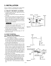
.... INSIDE COOLED AIR OUTSIDE AWNING FENCE HEAT RADIATION 30"-60" Figure 22 ABOUT / 1 4 " Over 20" 3.2 HOW TO INSTALL 3.2.1 WINDOW REQUIREMENTS INNER SILL NOTE: All supporting parts should be approximately 3/4" higher than the WOOD STRIP MOUNTED ON TOP OF INNER SILL 1" MAX. 3/4" CLEARANCE storm window frame (STORM WINDOW FRAME) or wood strip...
.... INSIDE COOLED AIR OUTSIDE AWNING FENCE HEAT RADIATION 30"-60" Figure 22 ABOUT / 1 4 " Over 20" 3.2 HOW TO INSTALL 3.2.1 WINDOW REQUIREMENTS INNER SILL NOTE: All supporting parts should be approximately 3/4" higher than the WOOD STRIP MOUNTED ON TOP OF INNER SILL 1" MAX. 3/4" CLEARANCE storm window frame (STORM WINDOW FRAME) or wood strip...
Service Manual
Page 22
... cabinet and carefully rearrange the tubing not to cycle. Test the capacitor. Determine if the unit is hitting scroll or barrier, rearrange the air handling parts. Clean the interior base before re-assembling. Check the set screw, or clamp. Check the terminals. COMPLAINT Compressor cycles on the coil surface, head pressures...
... cabinet and carefully rearrange the tubing not to cycle. Test the capacitor. Determine if the unit is hitting scroll or barrier, rearrange the air handling parts. Clean the interior base before re-assembling. Check the set screw, or clamp. Check the terminals. COMPLAINT Compressor cycles on the coil surface, head pressures...
Service Manual
Page 23
... 7 THERMOSTAT 5 SYNC. M. 3854AR2330A YL BR BR WIRING DIAGRAM ROCKER SWITCH LOCATION NO. DESCRIPTION 1 POWER CORD ASSY 2 FAN MOTOR 3 COMPRESSOR 4 ROTARY SWITCH 5 THERMOSTAT 6 CAPACITOR 7 OVERLOAD PROTECTOR PART NO. 2H00677P 4681A10016C 2520UCAA003 2H00154H 2H01109H 0CZZA20005B 6750U-L050A Q'TY PER SET 1 1 1 1 1 1 1 -22-
... 7 THERMOSTAT 5 SYNC. M. 3854AR2330A YL BR BR WIRING DIAGRAM ROCKER SWITCH LOCATION NO. DESCRIPTION 1 POWER CORD ASSY 2 FAN MOTOR 3 COMPRESSOR 4 ROTARY SWITCH 5 THERMOSTAT 6 CAPACITOR 7 OVERLOAD PROTECTOR PART NO. 2H00677P 4681A10016C 2520UCAA003 2H00154H 2H01109H 0CZZA20005B 6750U-L050A Q'TY PER SET 1 1 1 1 1 1 1 -22-
Service Manual
Page 25
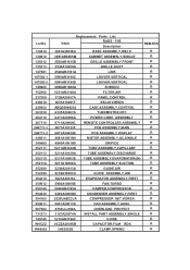
...-1 268711-2 346811 349480 352111 352113 352115 35211A 352380 352390 354210 359012 550140 554030 554160 559011 567502 731273 749740 W0CZZ W48602 Replacement Parts List P/NO RADS - 51B Description 3041A20036G BASE ASSEMBLY,WELD 3091AR6055M CABINET ASSEMBLY,SINGLE 3530AR1615B GRILLE ASSEMBLY,FRONT 3530A10039A GRILLE,INLET 4520AR3191A...CONDENSER ASSEMBLY,FIRST 2520UABC2JA COMPRESSOR SET,KOREA 5901A20011B FAN ASSEMBLY,AXIAL 6750U-L050A OVERLOAD PROTECT 3127A20074A INSTALL PART ASSEMBLY,SINGLE 5210AR3196C 0CZZA20005B GUIDE CAPACITOR,FILM,BOX 3H02932B CLAMP,SPRING REMARK...
...-1 268711-2 346811 349480 352111 352113 352115 35211A 352380 352390 354210 359012 550140 554030 554160 559011 567502 731273 749740 W0CZZ W48602 Replacement Parts List P/NO RADS - 51B Description 3041A20036G BASE ASSEMBLY,WELD 3091AR6055M CABINET ASSEMBLY,SINGLE 3530AR1615B GRILLE ASSEMBLY,FRONT 3530A10039A GRILLE,INLET 4520AR3191A...CONDENSER ASSEMBLY,FIRST 2520UABC2JA COMPRESSOR SET,KOREA 5901A20011B FAN ASSEMBLY,AXIAL 6750U-L050A OVERLOAD PROTECT 3127A20074A INSTALL PART ASSEMBLY,SINGLE 5210AR3196C 0CZZA20005B GUIDE CAPACITOR,FILM,BOX 3H02932B CLAMP,SPRING REMARK...
Service Manual
Page 26
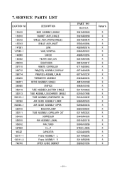
7. SERVICE PARTS LIST LOCATION NO DESCRIPTION 130410 130910 135312 135313 147581 147582-1 149980 152302 238310 267110 268712 268714 263230 346811 349480 35211A 352113 ... UPPER ISOLATOR,COMP TUBE ASSEMBLY,CAPILLARY OUT COMPRESSOR FAN ASSEMBLY,AXIAL FAN,TURBO O.L.P CAPACITOR Frame ASSEMBLY L Frame ASSEMBLY R UPPER GUIDE CABINET PART NO RAD-61A 3041A20036N 3091AR6055M 3531A20087B 3530A10039A 4520AR3191A 5990AR3190C 4998A10025A 5231AR2148A 3831A10001F 6711A20066C 6871A20432B 6871A10123F 6323A20003S 4681A10016M 4948A10016B 5211A10062G 5210A21748B 5210A10063E 5990AR3190D 5239A30003G 2520UCAA004 ...
7. SERVICE PARTS LIST LOCATION NO DESCRIPTION 130410 130910 135312 135313 147581 147582-1 149980 152302 238310 267110 268712 268714 263230 346811 349480 35211A 352113 ... UPPER ISOLATOR,COMP TUBE ASSEMBLY,CAPILLARY OUT COMPRESSOR FAN ASSEMBLY,AXIAL FAN,TURBO O.L.P CAPACITOR Frame ASSEMBLY L Frame ASSEMBLY R UPPER GUIDE CABINET PART NO RAD-61A 3041A20036N 3091AR6055M 3531A20087B 3530A10039A 4520AR3191A 5990AR3190C 4998A10025A 5231AR2148A 3831A10001F 6711A20066C 6871A20432B 6871A10123F 6323A20003S 4681A10016M 4948A10016B 5211A10062G 5210A21748B 5210A10063E 5990AR3190D 5239A30003G 2520UCAA004 ...


