Installation Instructions
Page 31
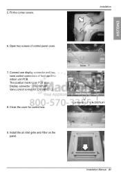
Connect one display connector and two vane control connectors of control panel cover. 7. Install the air inlet grille and Filter on PCB is as: Display connector : CN-DISPLAY Vane control connector: CN-VANE 1,2 8. 5. Installation Manual 31 Installation ENGLISH 6. The position marking on the panel. Close the cover for control box. Screw CN-VANE 1,2 CN-DISPLAY 9. Fit the corner covers. Open two screws of front panel to indoor unit PCB.
Connect one display connector and two vane control connectors of control panel cover. 7. Install the air inlet grille and Filter on PCB is as: Display connector : CN-DISPLAY Vane control connector: CN-VANE 1,2 8. 5. Installation Manual 31 Installation ENGLISH 6. The position marking on the panel. Close the cover for control box. Screw CN-VANE 1,2 CN-DISPLAY 9. Fit the corner covers. Open two screws of front panel to indoor unit PCB.

Service Manual
Page 4
All right reserved. 3. Inc. LGE Internal Use Only Th1 Th2 Th3 Description Thermistor for sunction air temperature Thermistor for evaporator inlet temperature Thermistor for training and service purposes -4- Only for evaporator outlet temperature PCB Connector CN_ROOM CN_PIPE/IN CN_PIPE/OUT Copyright ©2008 LG Electronics. Piping Diagrams Heating Heat exchanger Cooling Turbo fan Gas pipe connection port (flare connection) Th3 Th1 Th2 Liquid pipe connection port (flare connection) LOC.
All right reserved. 3. Inc. LGE Internal Use Only Th1 Th2 Th3 Description Thermistor for sunction air temperature Thermistor for evaporator inlet temperature Thermistor for training and service purposes -4- Only for evaporator outlet temperature PCB Connector CN_ROOM CN_PIPE/IN CN_PIPE/OUT Copyright ©2008 LG Electronics. Piping Diagrams Heating Heat exchanger Cooling Turbo fan Gas pipe connection port (flare connection) Th3 Th1 Th2 Liquid pipe connection port (flare connection) LOC.
