

Service Manual
Page 1
http://biz.lgservice.com KIMCHI REFRIGERATOR SERVICE MANUAL CAUTION PLEASE READ CAREFULLY THE SAFETY PRECAUTIONS OF THIS MANUAL BEFORE CHECKING OR OPERATING THE REFRIGERATOR. MODEL : GR-J303T*
http://biz.lgservice.com KIMCHI REFRIGERATOR SERVICE MANUAL CAUTION PLEASE READ CAREFULLY THE SAFETY PRECAUTIONS OF THIS MANUAL BEFORE CHECKING OR OPERATING THE REFRIGERATOR. MODEL : GR-J303T*

Service Manual
Page 2
... into electrical parts around the machine room. 6. Exploded View and Service Parts List ...34 -2- Product Specifications ...3 2. Especially, take care of Circuits ...6 4. SAFETY INSTRUCTIONS 1. Exercise care so that gas inside of the product. 2. CONTENTS 1. Ensure to consult the repair and maintenance center shop when the cold storage cycle is electrical leakage in using the instruments. 5. Firstly check that things should not fall down by removing them cleanly on...
... into electrical parts around the machine room. 6. Exploded View and Service Parts List ...34 -2- Product Specifications ...3 2. Especially, take care of Circuits ...6 4. SAFETY INSTRUCTIONS 1. Exercise care so that gas inside of the product. 2. CONTENTS 1. Ensure to consult the repair and maintenance center shop when the cold storage cycle is electrical leakage in using the instruments. 5. Firstly check that things should not fall down by removing them cleanly on...

Service Manual
Page 3
1. GR-J303T* MODEL ITEMS Rating Net Capacity Capacity Top Compartment Middle/Bottom Compartment Dimensions (mm) Net Weight Motor Power Consumption Cooling Method Method Defrosting Start System End Evaporation Insulation Evaporation Dish Basket Storage Container Drawer Shelf Flap Door Low temperature Catalyst Deodorization Compressor Evaporator of Top Compartment Cooling Evaporator of Cycle Middle Compartment Condenser 2 EA Refirgerant Refrigerant Oil Defrosting Device GR-J303TG SPEC 115V/60Hz 300 L 156 L GR-J303TS SPEC 115V/60Hz 300 L 156 L 144 L 144 L 667...
1. GR-J303T* MODEL ITEMS Rating Net Capacity Capacity Top Compartment Middle/Bottom Compartment Dimensions (mm) Net Weight Motor Power Consumption Cooling Method Method Defrosting Start System End Evaporation Insulation Evaporation Dish Basket Storage Container Drawer Shelf Flap Door Low temperature Catalyst Deodorization Compressor Evaporator of Top Compartment Cooling Evaporator of Cycle Middle Compartment Condenser 2 EA Refirgerant Refrigerant Oil Defrosting Device GR-J303TG SPEC 115V/60Hz 300 L 156 L GR-J303TS SPEC 115V/60Hz 300 L 156 L 144 L 144 L 667...

Service Manual
Page 4
ITEMS P.T.C Overload Protector Fan Motor(Top) Fan Motor(Middle) Condenser Electrical System Rating Cooling Fan Motor Defrosting Top Heater Middle Front-C Heater Fuse-M(Top) Fuse-M(Middle) Protection Fuse Capacitor, R SPEC P6R8MD 4TM314TFB Ø110 Fan Ø110 Fan Ø110 Fan 115 V 140 W 115 V 180 W(Half wave 90 W) 120 V(UL) 7 W Cutted at 70 °C Cutted at 70 °C 250 V 9 A 14ʈ / 250Vac SPEC P6R8MD 4TM314TFB Ø...
ITEMS P.T.C Overload Protector Fan Motor(Top) Fan Motor(Middle) Condenser Electrical System Rating Cooling Fan Motor Defrosting Top Heater Middle Front-C Heater Fuse-M(Top) Fuse-M(Middle) Protection Fuse Capacitor, R SPEC P6R8MD 4TM314TFB Ø110 Fan Ø110 Fan Ø110 Fan 115 V 140 W 115 V 180 W(Half wave 90 W) 120 V(UL) 7 W Cutted at 70 °C Cutted at 70 °C 250 V 9 A 14ʈ / 250Vac SPEC P6R8MD 4TM314TFB Ø...

Service Manual
Page 6
...button in initial application of power, and the upper room is indicated as "Cabbage" "Mid". 2. MICOM becomes "Lock" status in "Lock" status, nor performs function. -6- 3. EXPLANATION OF FUNCTION 3-1-1. DISPLAY PART (1) BEST MODEL(GR-J303TG) (2) BETTER MODEL(GR-J303TS) Cabbage/Radish/ Mul Kimchi Vegetble/ Fruit Light Freezing... Frozen Food Chilled Food NOTCH Min Mid Max Min Mid Max Min Mid Max Min Mid Max Max Min Mid Max Temperature setting 1.0°...
...button in initial application of power, and the upper room is indicated as "Cabbage" "Mid". 2. MICOM becomes "Lock" status in "Lock" status, nor performs function. -6- 3. EXPLANATION OF FUNCTION 3-1-1. DISPLAY PART (1) BEST MODEL(GR-J303TG) (2) BETTER MODEL(GR-J303TS) Cabbage/Radish/ Mul Kimchi Vegetble/ Fruit Light Freezing... Frozen Food Chilled Food NOTCH Min Mid Max Min Mid Max Min Mid Max Min Mid Max Max Min Mid Max Temperature setting 1.0°...
Service Manual
Page 7
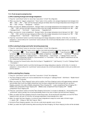
... can only be canceled. -7- 3-1-2. The Flavor Keeping function can use Flavor Keeping, operate in this time, if no button is "Vegetable/fruit", "Light freezing", it controls at this condition, the rhythm fermenting (seasoning) changes from "Fermented 1( )" ' "Fermented 2 ( )" ' "More fermented ( )" ' "Underground fermented( )" ' "Less fermented 1( )" ' "Less fermented 2( )", and the food type changes from "Min" ' "Mid". ("Cabbage Kimchi" ' "Old Kimchi" ' "Broth Kimchi...
... can only be canceled. -7- 3-1-2. The Flavor Keeping function can use Flavor Keeping, operate in this time, if no button is "Vegetable/fruit", "Light freezing", it controls at this condition, the rhythm fermenting (seasoning) changes from "Fermented 1( )" ' "Fermented 2 ( )" ' "More fermented ( )" ' "Underground fermented( )" ' "Less fermented 1( )" ' "Less fermented 2( )", and the food type changes from "Min" ' "Mid". ("Cabbage Kimchi" ' "Old Kimchi" ' "Broth Kimchi...

Service Manual
Page 9
... compartment sensor. (4) Operation conditions of the display button. 3. When you press the "Storage" button of the uppper compartment and the "Storage" button of refrigerator power. 2. When you press the button when the LCD back light is turned off , only the command to the upper compartment. 2. TEMPERATURE CONTROL AT UPPER, MIDDLE AND LOWER COMPARTMENT (1) Temperature control at middle/lower compartment 1.Turn COMP, middle compartment fan motor depending on . -9-
... compartment sensor. (4) Operation conditions of the display button. 3. When you press the "Storage" button of the uppper compartment and the "Storage" button of refrigerator power. 2. When you press the button when the LCD back light is turned off , only the command to the upper compartment. 2. TEMPERATURE CONTROL AT UPPER, MIDDLE AND LOWER COMPARTMENT (1) Temperature control at middle/lower compartment 1.Turn COMP, middle compartment fan motor depending on . -9-

Service Manual
Page 10
... room reaches to ambient temperature (weak cold in winter, excess cold in the test mode (turn on after power off for 20 minutes after starting defrost work. However, error status or test mode status is function of maintaining keeping temperature constantly irrespective of season by using the defrosting heater at the time of compressor operation time reaches to the operation order. 3-1-9. DEFROSTING (REMOVAL OF FROST) 1. It turns off in summer). However...
... room reaches to ambient temperature (weak cold in winter, excess cold in the test mode (turn on after power off for 20 minutes after starting defrost work. However, error status or test mode status is function of maintaining keeping temperature constantly irrespective of season by using the defrosting heater at the time of compressor operation time reaches to the operation order. 3-1-9. DEFROSTING (REMOVAL OF FROST) 1. It turns off in summer). However...

Service Manual
Page 11
... upper & middle compartment, fan motor at the upper & middle compartment, single motor damper and FRONT-C heater sequentially operate as followers for preventing noise and damage of parts occurred by that various parts operate at the same time in input of initial power on and after test closing (including temporary power failure, either): Function Operation Sequence Remarks When defrosting sensor temperature at the upper compartment...
... upper & middle compartment, fan motor at the upper & middle compartment, single motor damper and FRONT-C heater sequentially operate as followers for preventing noise and damage of parts occurred by that various parts operate at the same time in input of initial power on and after test closing (including temporary power failure, either): Function Operation Sequence Remarks When defrosting sensor temperature at the upper compartment...
Service Manual
Page 12
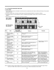
... the button in occurrence of the reed-S/W is released during use occurs. 2. FAILURE DIAGNOSIS FUNCTION (1) Failure Mode 1. 3-1-13. The product returns to normal operation if failure is not Damper motor damaged, dP dectected even when driving the single frozen, coil damaged, driving motor damper for a second where poor ambient temperature sensor exists. - 12 - BEST MODEL (GR-J303TG) BETTER MODEL (GR-J303TS) NO...
... the button in occurrence of the reed-S/W is released during use occurs. 2. FAILURE DIAGNOSIS FUNCTION (1) Failure Mode 1. 3-1-13. The product returns to normal operation if failure is not Damper motor damaged, dP dectected even when driving the single frozen, coil damaged, driving motor damper for a second where poor ambient temperature sensor exists. - 12 - BEST MODEL (GR-J303TG) BETTER MODEL (GR-J303TS) NO...

Service Manual
Page 14
.... 5. Defrost heater OFF at middle/lower compartment and 3-way valve operates to normal status. 3. COMP (* Fan motor at middle, lower compartment are closed. 6. 3-way valve maintains previous status. 7. All dampers at machine room) OFF 2. It is neither detected, nor button recognition sound comes out during the test mode. 4. 3-1-14. For display, the only "Min" LED of the upper room turns on...
.... 5. Defrost heater OFF at middle/lower compartment and 3-way valve operates to normal status. 3. COMP (* Fan motor at middle, lower compartment are closed. 6. 3-way valve maintains previous status. 7. All dampers at machine room) OFF 2. It is neither detected, nor button recognition sound comes out during the test mode. 4. 3-1-14. For display, the only "Min" LED of the upper room turns on...

Service Manual
Page 15
... power failure. During general operation, the reset terminal is at the IC1 changes where SPEC changes. 3-2-3. POWER CIRCUIT Power circuits consist of SMPS (Switching Mode Power Supply) power, and the SMPS consists of the rectification part (BD1, CE1) to convert AC voltage to DC voltage, the switching part (IC3) to switch the converted DC voltage, a transformer to transfer energy of the primary side on the switching terminal, secondary side power to supply power...
... power failure. During general operation, the reset terminal is at the IC1 changes where SPEC changes. 3-2-3. POWER CIRCUIT Power circuits consist of SMPS (Switching Mode Power Supply) power, and the SMPS consists of the rectification part (BD1, CE1) to convert AC voltage to DC voltage, the switching part (IC3) to switch the converted DC voltage, a transformer to transfer energy of the primary side on the switching terminal, secondary side power to supply power...

Service Manual
Page 19
... irrespective of temperature to detect open/close status of the reed switch. - 19 - Single Motor Damper 100V~127V deleted 4. Drives the motor, and if there is time until the single motor stops after status change of the reed switch within 2 minutes, determines it as failure and displays as electronic single motor damper, to open or close the baffle and the reed switch part to...
... irrespective of temperature to detect open/close status of the reed switch. - 19 - Single Motor Damper 100V~127V deleted 4. Drives the motor, and if there is time until the single motor stops after status change of the reed switch within 2 minutes, determines it as failure and displays as electronic single motor damper, to open or close the baffle and the reed switch part to...

Service Manual
Page 34
EXPLODED VIEW u GR-J303T* 103B 103A 411A 410G 501A 501F 501K 610E 281A 281B 619B 301A 401A 404A 405C 405A 329A 304A 108A 605A 105B 184C 105A 109B 316A 307A 314A 318A 317A 327B 310A 308A 309A 619A 319D 329C 309B 323B 315C 104B 106A 103C 312A 328A 420A 319A 315B 319C 315B 315A 418A 282B 406B 330B 401B 332B 109B 301B 418B 104A 106A 331D 404B 405C 405A 329B 332C 245A - 34 - EXPLODED VIEW AND SERVICE PARTS LIST 4-1. 4.
EXPLODED VIEW u GR-J303T* 103B 103A 411A 410G 501A 501F 501K 610E 281A 281B 619B 301A 401A 404A 405C 405A 329A 304A 108A 605A 105B 184C 105A 109B 316A 307A 314A 318A 317A 327B 310A 308A 309A 619A 319D 329C 309B 323B 315C 104B 106A 103C 312A 328A 420A 319A 315B 319C 315B 315A 418A 282B 406B 330B 401B 332B 109B 301B 418B 104A 106A 331D 404B 405C 405A 329B 332C 245A - 34 - EXPLODED VIEW AND SERVICE PARTS LIST 4-1. 4.

Service Manual
Page 39
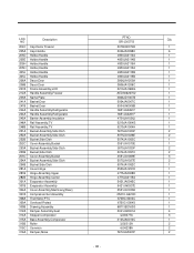
... Handle,Rear Handle,Rear Cover,Lower Leg Assembly,Frame Leg Assembly,Frame Tube Assembly,Drain Tube Assembly,Drain Leg,Adjust Leg,Adjust Tray Assembly,Drain Cap,Screw Door Assembly,Freeze Room Stopper,Door Shelf Assembly,Freezer Shelf Shelf,Glass Door Assembly,Freeze Room Stopper,Door Guide,Rail Guide,Rail Shelf Assembly,Freezer Door Assembly,Freeze Room Basket Bucket Assembly,Side Dish Bucket,Side Dish Cover Assembly,Bucket Guide Assembly,Rail Guide Assembly,Rail Bucket Assembly,Side Dish Bucket,Side Dish Cover Assembly,Bucket Cover Assembly,Deodorizer Cover,Deodorizer Cover,Deodorizer...
... Handle,Rear Handle,Rear Cover,Lower Leg Assembly,Frame Leg Assembly,Frame Tube Assembly,Drain Tube Assembly,Drain Leg,Adjust Leg,Adjust Tray Assembly,Drain Cap,Screw Door Assembly,Freeze Room Stopper,Door Shelf Assembly,Freezer Shelf Shelf,Glass Door Assembly,Freeze Room Stopper,Door Guide,Rail Guide,Rail Shelf Assembly,Freezer Door Assembly,Freeze Room Basket Bucket Assembly,Side Dish Bucket,Side Dish Cover Assembly,Bucket Guide Assembly,Rail Guide Assembly,Rail Bucket Assembly,Side Dish Bucket,Side Dish Cover Assembly,Bucket Cover Assembly,Deodorizer Cover,Deodorizer Cover,Deodorizer...
Service Manual
Page 40
... Holder,Handle Holder,Handle Decor,Door Decor,Door Frame Assembly,LCD Handle Assembly,Freezer Name Plate Basket,Door Basket,Door Handle Assembly,Refrigerator Handle Assembly,Refrigerator Barrier Assembly,Insulation Rail Assembly,TV Rail Assembly,TV Bucket Assembly,Side Dish Bucket Assembly,Side Dish Bucket,Side Dish Cover Assembly,Bucket Bucket Assembly,Side Dish Bucket,Side Dish Cover Assembly,Bucket Bucket Assembly,Side Dish Bucket,Side Dish Cover,Hinge Hinge Assembly,Upper Hinge Assembly,Center Evaporator Assembly Evaporator Assembly Cover Assembly,Machinery(Rear) Compressor,Set Assembly...
... Holder,Handle Holder,Handle Decor,Door Decor,Door Frame Assembly,LCD Handle Assembly,Freezer Name Plate Basket,Door Basket,Door Handle Assembly,Refrigerator Handle Assembly,Refrigerator Barrier Assembly,Insulation Rail Assembly,TV Rail Assembly,TV Bucket Assembly,Side Dish Bucket Assembly,Side Dish Bucket,Side Dish Cover Assembly,Bucket Bucket Assembly,Side Dish Bucket,Side Dish Cover Assembly,Bucket Bucket Assembly,Side Dish Bucket,Side Dish Cover,Hinge Hinge Assembly,Upper Hinge Assembly,Center Evaporator Assembly Evaporator Assembly Cover Assembly,Machinery(Rear) Compressor,Set Assembly...
Service Manual
Page 41
... Tray,Drip Guide,Fan Bracket,Valve Condenser Assembly,Wire Damper Damper,Pipe Fan Assembly Fan Assembly Fan Assembly Shroud Assembly,Freezer Shroud,Freezer Grille Assembly,Fan Grille Assembly,Fan Controller Assembly Controller Assembly AC Motor AC Motor Bracket,Motor Damper,Motor Support Damper,Motor Support Switch,Push Button Capacitor,Electric Appliance Film,Radial Capacitor,Electric Appliance Film,Radial Power Cord Assembly Heater,Sheath Heater,Sheath Motor,DC PCB Assembly,Main Cover,PCB Case,PCB Deodorizer Cover,Deodorizer Roller Assembly Cover,Sensor Valve Assembly,Pipe Valve Assembly...
... Tray,Drip Guide,Fan Bracket,Valve Condenser Assembly,Wire Damper Damper,Pipe Fan Assembly Fan Assembly Fan Assembly Shroud Assembly,Freezer Shroud,Freezer Grille Assembly,Fan Grille Assembly,Fan Controller Assembly Controller Assembly AC Motor AC Motor Bracket,Motor Damper,Motor Support Damper,Motor Support Switch,Push Button Capacitor,Electric Appliance Film,Radial Capacitor,Electric Appliance Film,Radial Power Cord Assembly Heater,Sheath Heater,Sheath Motor,DC PCB Assembly,Main Cover,PCB Case,PCB Deodorizer Cover,Deodorizer Roller Assembly Cover,Sensor Valve Assembly,Pipe Valve Assembly...

Service Manual
Page 42
... Assembly,Drain Tube Assembly,Drain Leg,Adjust Leg,Adjust Tray Assembly,Drain Cap,Screw Door Assembly,Freeze Room Tray Assembly,Drawer Tray Assembly,Drawer Guide Assembly,Rail Guide Assembly,Rail Cover Assembly,Deodorizer Cover,Deodorizer Cover,Deodorizer Deodorizer Roller Assembly Roller Assembly Plate,Center Door Foam Assembly Door Foam Assembly,Refrigerator Door Foam Assembly,Refrigerator Stopper,Door Gasket Assembly,Door Gasket Assembly,Door Gasket Assembly,Door Cap,Decor Freezer Cap,Handle Holder,Handle Holder,Handle Holder,Handle Holder,Handle Holder,Handle Decor,Door Decor,Door Panel...
... Assembly,Drain Tube Assembly,Drain Leg,Adjust Leg,Adjust Tray Assembly,Drain Cap,Screw Door Assembly,Freeze Room Tray Assembly,Drawer Tray Assembly,Drawer Guide Assembly,Rail Guide Assembly,Rail Cover Assembly,Deodorizer Cover,Deodorizer Cover,Deodorizer Deodorizer Roller Assembly Roller Assembly Plate,Center Door Foam Assembly Door Foam Assembly,Refrigerator Door Foam Assembly,Refrigerator Stopper,Door Gasket Assembly,Door Gasket Assembly,Door Gasket Assembly,Door Cap,Decor Freezer Cap,Handle Holder,Handle Holder,Handle Holder,Handle Holder,Handle Holder,Handle Decor,Door Decor,Door Panel...

Service Manual
Page 43
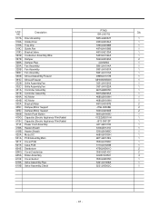
...,Side Dish Cover Assembly,Bucket Bucket Assembly,Side Dish Bucket,Side Dish Cover Assembly,Bucket Bucket Assembly,Side Dish Bucket,Side Dish Frame Assembly,Display Cover,Hinge Hinge Assembly,Upper Hinge Assembly,Center Evaporator Assembly Evaporator Assembly Cover Assembly,Machinery(Rear) Compressor,Set Assembly Thermistor,PTC Overload Protect Drawing,Assembly Damper Assembly,Seat Stopper,Compressor Base Assembly,Compressor Roller Common Damper,Noise Drier Assembly Holder,Drier Tray,Drip Guide,Fan Bracket,Valve Condenser Assembly,Wire Damper PTNO Qty GR-J303TS 3846JD1007B 1 5004JA0007C...
...,Side Dish Cover Assembly,Bucket Bucket Assembly,Side Dish Bucket,Side Dish Cover Assembly,Bucket Bucket Assembly,Side Dish Bucket,Side Dish Frame Assembly,Display Cover,Hinge Hinge Assembly,Upper Hinge Assembly,Center Evaporator Assembly Evaporator Assembly Cover Assembly,Machinery(Rear) Compressor,Set Assembly Thermistor,PTC Overload Protect Drawing,Assembly Damper Assembly,Seat Stopper,Compressor Base Assembly,Compressor Roller Common Damper,Noise Drier Assembly Holder,Drier Tray,Drip Guide,Fan Bracket,Valve Condenser Assembly,Wire Damper PTNO Qty GR-J303TS 3846JD1007B 1 5004JA0007C...
Service Manual
Page 44
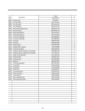
...619A 619B Description Damper,Pipe Fan Assembly Fan Assembly Fan Assembly Shroud Assembly,Freezer Shroud,Freezer Grille Assembly,Fan Grille Assembly,Fan Controller Assembly Controller Assembly AC Motor AC Motor Bracket,Motor Damper,Motor Support Switch,Push Button Capacitor,Electric Appliance Film,Radial Capacitor,Electric Appliance Film,Radial Power Cord Assembly Heater,Sheath Heater,Sheath Motor,DC PCB Assembly,Main Cover,PCB Case,PCB Deodorizer Cover,Deodorizer Roller Assembly Cover,Sensor Valve Assembly,Pipe Valve Assembly,Check PTNO Qty GR-J303TS 4J03020A 1 5901JA1014A 1 5901JA1007A...
...619A 619B Description Damper,Pipe Fan Assembly Fan Assembly Fan Assembly Shroud Assembly,Freezer Shroud,Freezer Grille Assembly,Fan Grille Assembly,Fan Controller Assembly Controller Assembly AC Motor AC Motor Bracket,Motor Damper,Motor Support Switch,Push Button Capacitor,Electric Appliance Film,Radial Capacitor,Electric Appliance Film,Radial Power Cord Assembly Heater,Sheath Heater,Sheath Motor,DC PCB Assembly,Main Cover,PCB Case,PCB Deodorizer Cover,Deodorizer Roller Assembly Cover,Sensor Valve Assembly,Pipe Valve Assembly,Check PTNO Qty GR-J303TS 4J03020A 1 5901JA1014A 1 5901JA1007A...


