

Owner's Manual
Page 1
LED LCD MONITOR MODELS E1960S E1960T E2060S E2060T E2260S E2260T E2260V E2360S E2360T E2360V www.lg.com ENGLISH OWNER'S MANUAL LED LCD MONITOR Please read this manual carefully before operating your set and retain it for future reference.
LED LCD MONITOR MODELS E1960S E1960T E2060S E2060T E2260S E2260T E2260V E2360S E2360T E2360V www.lg.com ENGLISH OWNER'S MANUAL LED LCD MONITOR Please read this manual carefully before operating your set and retain it for future reference.
Owner's Manual
Page 4
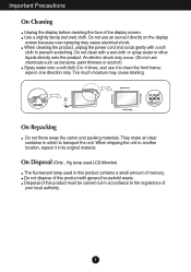
... alcohol) Spray water onto a soft cloth 2 to the regulations of mercury. An electric shock may cause electrical shock. On Disposal (Only , Hg lamp used LCD Monitor) The fluorescent lamp used in this product must be carried out in accordance to 4 times, and use it in its original material. Use a slightly damp...
... alcohol) Spray water onto a soft cloth 2 to the regulations of mercury. An electric shock may cause electrical shock. On Disposal (Only , Hg lamp used LCD Monitor) The fluorescent lamp used in this product must be carried out in accordance to 4 times, and use it in its original material. Use a slightly damp...
Owner's Manual
Page 5
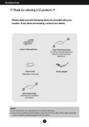
... included with ferrite cores to this signal cable may look different from those shown here. Please make sure the following items are missing, contact your monitor. Thank for the product. 4 Accessories !!!
... included with ferrite cores to this signal cable may look different from those shown here. Please make sure the following items are missing, contact your monitor. Thank for the product. 4 Accessories !!!

Owner's Manual
Page 6
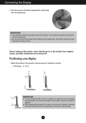
Place the monitor face down on the cushion or soft cloth. 2. Attach the monitor to the Stand Base by using the screw handle. 4. Assemble the Stand Base into the Stand Body in the correct direction as shown in the picture. Once assembled take the monitor up the monitor, ensure that the power to the right. Screw : Turn the screw by turning the screw to the monitor, the computer system, and other attached devices is turned off. Stand Body Stand Base 3. Connecting the stand 1. Connecting the Display Before setting up carefully and face the front side. 5
Place the monitor face down on the cushion or soft cloth. 2. Attach the monitor to the Stand Base by using the screw handle. 4. Assemble the Stand Base into the Stand Body in the correct direction as shown in the picture. Once assembled take the monitor up the monitor, ensure that the power to the right. Screw : Turn the screw by turning the screw to the monitor, the computer system, and other attached devices is turned off. Stand Body Stand Base 3. Connecting the stand 1. Connecting the Display Before setting up carefully and face the front side. 5
Owner's Manual
Page 7
...Positioning your finger(s) in between the head of the panel in various ways for maximum comfort. IMPORTANT This illustration depicts the general model of the monitor should not exceed 5 degrees. The product may differ from the stand base. Connecting the Display Turn the screw to the left to separate the... stand body from the items shown in the picture. Before setting up the monitor, ensure that in order to the monitor, the computer system, and other attached devices is turned off. You can hurt your foot. Tilt Range : -5˚ to 15˚...
...Positioning your finger(s) in between the head of the panel in various ways for maximum comfort. IMPORTANT This illustration depicts the general model of the monitor should not exceed 5 degrees. The product may differ from the stand base. Connecting the Display Turn the screw to the left to separate the... stand body from the items shown in the picture. Before setting up the monitor, ensure that in order to the monitor, the computer system, and other attached devices is turned off. You can hurt your foot. Tilt Range : -5˚ to 15˚...
Owner's Manual
Page 8
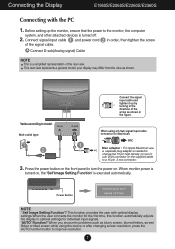
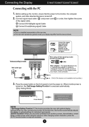
... Power Button NOTE ' Self Image Setting Function'? Wall-outlet type Connect the signal input cable and tighten it up the monitor, ensure that the power to the monitor, the computer system, and other attached devices is needed to improve resolution. 7 Press the power button on the front panel...the 15 pin high density (3 row) D- Connect signal input cable 1 and power cord 2 in the direction of the arrow as shown. When monitor power is turned on, the 'Self Image Setting Function' is a simplified representation of the signal cable. When you encounter problems such as blurry screen...
... Power Button NOTE ' Self Image Setting Function'? Wall-outlet type Connect the signal input cable and tighten it up the monitor, ensure that the power to the monitor, the computer system, and other attached devices is needed to improve resolution. 7 Press the power button on the front panel...the 15 pin high density (3 row) D- Connect signal input cable 1 and power cord 2 in the direction of the arrow as shown. When monitor power is turned on, the 'Self Image Setting Function' is a simplified representation of the signal cable. When you encounter problems such as blurry screen...
Owner's Manual
Page 9
Connecting the Display E1960T/E2060T/E2260T/E2360T Connecting with optimal display settings.When the user connects the monitor for the first time, this function automatically adjusts the display to optimal settings for Macintosh Mac adapter : For Apple Macintosh use, a separate plug adapter is... the supplied cable to a 15 pin 2 row connector. Varies according to turn the power on , the 'Self Image Setting Function' is turned off. 2. When monitor power is turned on . Connect signal input cable 1 and power cord 2 in order, then tighten the screw of the arrow as shown in all countries...
Connecting the Display E1960T/E2060T/E2260T/E2360T Connecting with optimal display settings.When the user connects the monitor for the first time, this function automatically adjusts the display to optimal settings for Macintosh Mac adapter : For Apple Macintosh use, a separate plug adapter is... the supplied cable to a 15 pin 2 row connector. Varies according to turn the power on , the 'Self Image Setting Function' is turned off. 2. When monitor power is turned on . Connect signal input cable 1 and power cord 2 in order, then tighten the screw of the arrow as shown in all countries...
Owner's Manual
Page 10
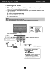
... arrow as shown. This rear view represents a general model; Headphone/Earphone Input DVI-D (This feature is turned off. 2. Varies according to the monitor, the computer system, and other attached devices is not available in the figure. Connecting the Display E2260V/E2360V Connecting with the PC 1. A Connect ...Dsub VGA connector on the AV equipment. * Not supported PC Wall-outlet type Connect the signal input cable and tighten it up the monitor, ensure that the power to model. Connect signal input cable 1 and power cord 2 in order, then tighten the screw of the rear view....
... arrow as shown. This rear view represents a general model; Headphone/Earphone Input DVI-D (This feature is turned off. 2. Varies according to the monitor, the computer system, and other attached devices is not available in the figure. Connecting the Display E2260V/E2360V Connecting with the PC 1. A Connect ...Dsub VGA connector on the AV equipment. * Not supported PC Wall-outlet type Connect the signal input cable and tighten it up the monitor, ensure that the power to model. Connect signal input cable 1 and power cord 2 in order, then tighten the screw of the rear view....

Owner's Manual
Page 11
... Display E2260V/E2360V 3. Press the power button on the front panel to turn the power on , the 'Self Image Setting Function' is turned on . When monitor power is executed automatically. (Only Analog Mode) Power Button NOTE ' Self Image Setting Function'? When you encounter problems such as blurry screen, blurred letters, screen...
... Display E2260V/E2360V 3. Press the power button on the front panel to turn the power on , the 'Self Image Setting Function' is turned on . When monitor power is executed automatically. (Only Analog Mode) Power Button NOTE ' Self Image Setting Function'? When you encounter problems such as blurry screen, blurred letters, screen...
Owner's Manual
Page 20
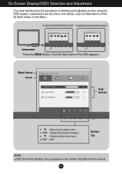
Listed below are the icons, icon names, and icon descriptions of selecting and adjusting an item using the OSD system. On Screen Display(OSD) Selection and Adjustment You were introduced to the upper menu Adjust (Decrease/Increase) Select another sub-menu Exit Button Tip NOTE OSD (On Screen Display) menu languages on the Menu. Menu Name Icons Submenus Move to the procedure of the all items shown on the monitor may differ from the manual. 19 E1960T/E2060T/E2260T/E2360T E1960S/E2060S/E2260S/E2360S Press the MENU Button, then the main menu of the OSD appears.
Listed below are the icons, icon names, and icon descriptions of selecting and adjusting an item using the OSD system. On Screen Display(OSD) Selection and Adjustment You were introduced to the upper menu Adjust (Decrease/Increase) Select another sub-menu Exit Button Tip NOTE OSD (On Screen Display) menu languages on the Menu. Menu Name Icons Submenus Move to the procedure of the all items shown on the monitor may differ from the manual. 19 E1960T/E2060T/E2260T/E2360T E1960S/E2060S/E2260S/E2360S Press the MENU Button, then the main menu of the OSD appears.
Owner's Manual
Page 21
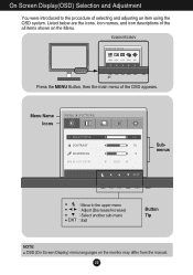
Listed below are the icons, icon names, and icon descriptions of the OSD appears. E2260V/E2360V Press the MENU Button, then the main menu of the all items shown on the monitor may differ from the manual. 20 On Screen Display(OSD) Selection and Adjustment You were introduced to the upper menu Adjust (Decrease/Increase) Select another sub-menu Exit Button Tip NOTE OSD (On Screen Display) menu languages on the Menu. Menu Name Icons Submenus Move to the procedure of selecting and adjusting an item using the OSD system.
Listed below are the icons, icon names, and icon descriptions of the OSD appears. E2260V/E2360V Press the MENU Button, then the main menu of the all items shown on the monitor may differ from the manual. 20 On Screen Display(OSD) Selection and Adjustment You were introduced to the upper menu Adjust (Decrease/Increase) Select another sub-menu Exit Button Tip NOTE OSD (On Screen Display) menu languages on the Menu. Menu Name Icons Submenus Move to the procedure of selecting and adjusting an item using the OSD system.

Owner's Manual
Page 22
... screen will be dark. (only for video signal, it is the darkest screen the monitor can set the offset level. On Screen Display(OSD) Selection and Adjustment Main menu Sub menu Description E1960S/E2060S/E2260S/E2360S E1960T/E2060T/E2260T/E2360T BRIGHTNESS To adjust the brightness of the screen. As the criteria for...
... screen will be dark. (only for video signal, it is the darkest screen the monitor can set the offset level. On Screen Display(OSD) Selection and Adjustment Main menu Sub menu Description E1960S/E2060S/E2260S/E2360S E1960T/E2060T/E2260T/E2360T BRIGHTNESS To adjust the brightness of the screen. As the criteria for...

Owner's Manual
Page 23
... color levels. BLUE Set your own green color levels. USER Mode : Move to 9300K: Slightly bluish white. RED Set your own gamma value. : 0 / 1 / 2 On the monitor, high gamma values display whitish images and low gamma values display blackish images. USER Mode PRESET USER Select the screen color. • sRGB: Set the... Mode GAMMA Set your own red color levels. On Screen Display(OSD) Selection and Adjustment Main menu Sub menu Description E1960S/E2060S/E2260S/E2360S E1960T/E2060T/E2260T/E2360T PRESET Mode COLOR TEMP Select either PRESET or USER to adjust the screen color.
... color levels. BLUE Set your own green color levels. USER Mode : Move to 9300K: Slightly bluish white. RED Set your own gamma value. : 0 / 1 / 2 On the monitor, high gamma values display whitish images and low gamma values display blackish images. USER Mode PRESET USER Select the screen color. • sRGB: Set the... Mode GAMMA Set your own red color levels. On Screen Display(OSD) Selection and Adjustment Main menu Sub menu Description E1960S/E2060S/E2260S/E2360S E1960T/E2060T/E2260T/E2360T PRESET Mode COLOR TEMP Select either PRESET or USER to adjust the screen color.

Owner's Manual
Page 26
... the input signal is different the required specifications, the color level may deteriorate due to reset immediately. If the output of the monitor to provide the optimal image. Activate this function to set ON at any time, the power indicator will be turned on the ... factory default settings except "LANGUAGE." On Screen Display(OSD) Selection and Adjustment Main menu Sub menu Description E1960S/E2060S/E2260S/E2360S E1960T/E2060T/E2260T/E2360T D-SUB input LANGUAGE POWER INDICATOR DVI-D input WHITE BALANCE E2260V/E2360V D-SUB input FACTORY RESET To choose the language in ...
... the input signal is different the required specifications, the color level may deteriorate due to reset immediately. If the output of the monitor to provide the optimal image. Activate this function to set ON at any time, the power indicator will be turned on the ... factory default settings except "LANGUAGE." On Screen Display(OSD) Selection and Adjustment Main menu Sub menu Description E1960S/E2060S/E2260S/E2360S E1960T/E2060T/E2260T/E2360T D-SUB input LANGUAGE POWER INDICATOR DVI-D input WHITE BALANCE E2260V/E2360V D-SUB input FACTORY RESET To choose the language in ...

Owner's Manual
Page 27
E1960T/E2060T/E2260T/E2360T E2260V/E2360V E1960S/E2060S/E2260S/E2360S Press the MODE Button, then the main menu of selecting and adjusting an item using the OSD system. Menu Name Icons Submenus Move to the procedure of the OSD appears. On Screen Display(OSD) Selection and Adjustment You were introduced to the upper menu Move Select another sub-menu Exit Button Tip NOTE OSD (On Screen Display) menu languages on the Menu. Listed below are the icons, icon names, and icon descriptions of the all items shown on the monitor may differ from the manual. 26
E1960T/E2060T/E2260T/E2360T E2260V/E2360V E1960S/E2060S/E2260S/E2360S Press the MODE Button, then the main menu of selecting and adjusting an item using the OSD system. Menu Name Icons Submenus Move to the procedure of the OSD appears. On Screen Display(OSD) Selection and Adjustment You were introduced to the upper menu Move Select another sub-menu Exit Button Tip NOTE OSD (On Screen Display) menu languages on the Menu. Listed below are the icons, icon names, and icon descriptions of the all items shown on the monitor may differ from the manual. 26

Owner's Manual
Page 31
ORIGINAL Change the input image signal ratio to original. * This function works only if input resolution is lower than monitor ratio (16:9). : Move to input image signal. On Screen Display(OSD) Selection and Adjustment Main menu Sub menu Description WIDE Switch to full screen mode according to the upper menu , : Move EXIT : Exit 30
ORIGINAL Change the input image signal ratio to original. * This function works only if input resolution is lower than monitor ratio (16:9). : Move to input image signal. On Screen Display(OSD) Selection and Adjustment Main menu Sub menu Description WIDE Switch to full screen mode according to the upper menu , : Move EXIT : Exit 30
Owner's Manual
Page 35
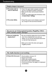
... (true color) at Control Panel - Or, you installed the display driver? • Be sure to install the display driver from our web site: http://www.lg.com. • Make sure to check if the video card supports Plug&Play function. Troubleshooting Display image is incorrect G The screen color is mono or... is "0". • Check sound muted. • HDMI cable installed properly. • Head phone cable installed properly. • Check sound format. Do you see an "Unrecognized monitor, Plug&Play (VESA DDC) monitor found" message? Not supply to compressed sound format. 34
... (true color) at Control Panel - Or, you installed the display driver? • Be sure to install the display driver from our web site: http://www.lg.com. • Make sure to check if the video card supports Plug&Play function. Troubleshooting Display image is incorrect G The screen color is mono or... is "0". • Check sound muted. • HDMI cable installed properly. • Head phone cable installed properly. • Check sound format. Do you see an "Unrecognized monitor, Plug&Play (VESA DDC) monitor found" message? Not supply to compressed sound format. 34


