
Service Manual
Page 3
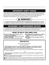
... failure may result in anti-static bag, observe above instructions. 2 The new control assembly may damage or weaken the electronic control assembly. Avoid touching electronic parts or terminal contacts; If electrical power is required for service, they must be responsible for the interpretation of all occupants. Follow the gas supplier's instructions.... WARNING ! WHAT TO DO IF YOU SMELL GAS: Do not try to green ground connection point or unpainted metal in the appliance. Before removing the part from a neighbor's phone.
... failure may result in anti-static bag, observe above instructions. 2 The new control assembly may damage or weaken the electronic control assembly. Avoid touching electronic parts or terminal contacts; If electrical power is required for service, they must be responsible for the interpretation of all occupants. Follow the gas supplier's instructions.... WARNING ! WHAT TO DO IF YOU SMELL GAS: Do not try to green ground connection point or unpainted metal in the appliance. Before removing the part from a neighbor's phone.

Service Manual
Page 4
COMPONENT TESTING INFORMATION 14 6. MOTOR DIAGRAM AND SCHEMATIC 17 7. WIRING DIAGRAM ...19 9. TEST 7 GAS VALVE TEST - DRUM & MOTOR ASSEMBLY: GAS MODEL 42 13. REPLACEMENT PARTS LIST 43 3 FEATURES AND BENEFITS ...6 3. GAS MODEL 28 9-8 TEST 8 SEMI-CONDUCTOR 29 10. CONTROL PANEL & PLATE ASSEMBLY 39 12-2. TEST 2 THERMISTOR TEST 22 9-3. TEST 5 DOOR ...
COMPONENT TESTING INFORMATION 14 6. MOTOR DIAGRAM AND SCHEMATIC 17 7. WIRING DIAGRAM ...19 9. TEST 7 GAS VALVE TEST - DRUM & MOTOR ASSEMBLY: GAS MODEL 42 13. REPLACEMENT PARTS LIST 43 3 FEATURES AND BENEFITS ...6 3. GAS MODEL 28 9-8 TEST 8 SEMI-CONDUCTOR 29 10. CONTROL PANEL & PLATE ASSEMBLY 39 12-2. TEST 2 THERMISTOR TEST 22 9-3. TEST 5 DOOR ...
Service Manual
Page 9
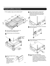
... the dryer on a solid and level floor for dryer 5 Be sure to press the adhesive parts of the pedestal. , for washer/ combo for proper operation. Adjust the legs of side brackets...holding the pedestal leg using a wrench. 8 Pedestal Installation Instructions For washer, dryer, and combo LG 27" 4 AAtftaecr hretmheovdinogubthle-pfarocteedcttivaepecoovfetrhinegbfroamcktehteto the dardyheersaivsesshuorfwacnes, oaltighne tbhenstcpreawrtshoolfetshien bthreackets ablriagcnkwetisthwtihthetheedgmeaatcnhdincgahnoblees aintttahcehpeeddteostahle pbeadseesatnadl wpritehssscarnedwpsr.ess the...
... the dryer on a solid and level floor for dryer 5 Be sure to press the adhesive parts of the pedestal. , for washer/ combo for proper operation. Adjust the legs of side brackets...holding the pedestal leg using a wrench. 8 Pedestal Installation Instructions For washer, dryer, and combo LG 27" 4 AAtftaecr hretmheovdinogubthle-pfarocteedcttivaepecoovfetrhinegbfroamcktehteto the dardyheersaivsesshuorfwacnes, oaltighne tbhenstcpreawrtshoolfetshien bthreackets ablriagcnkwetisthwtihthetheedgmeaatcnhdincgahnoblees aintttahcehpeeddteostahle pbeadseesatnadl wpritehssscarnedwpsr.ess the...
Service Manual
Page 32
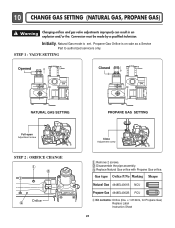
... SETTING Opened Closed Full open Adjustment screw STEP 2 : ORIFICE CHANGE Orifice Close Adjustment screw Remove 2 screws. Initially, Natural Gas mode is on sale as a Service Part to authorized servicers only. Disassemble the pipe assembly. Propane Gas Orifice is set. Replace Natural Gas orifice with Propane Gas orifice. Gas type Orifice P/No...
... SETTING Opened Closed Full open Adjustment screw STEP 2 : ORIFICE CHANGE Orifice Close Adjustment screw Remove 2 screws. Initially, Natural Gas mode is on sale as a Service Part to authorized servicers only. Disassemble the pipe assembly. Propane Gas Orifice is set. Replace Natural Gas orifice with Propane Gas orifice. Gas type Orifice P/No...

Service Manual
Page 38
... to take gloves and careful exhaust edge. DUCT TAPE 3-2. DUCT TAPE 2-2. When you disassemble and install ventilation, be sure to the base. (Duct is a SVC part) DUCT TAPE 3-1.
... to take gloves and careful exhaust edge. DUCT TAPE 3-2. DUCT TAPE 2-2. When you disassemble and install ventilation, be sure to the base. (Duct is a SVC part) DUCT TAPE 3-1.
Service Manual
Page 45
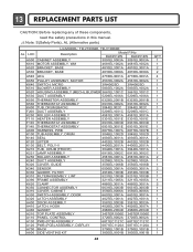
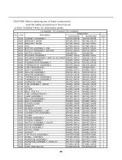
... CAUTION: Before replacing any of these components, read the safety precautions in this manual. ¡Æ Note: S(Safety Parts), AL (Alternative parts) LG MODEL: TD-V10062E, TD-V10060E AL LOC Description Model P/No DLE2512W DLE2514W A500 CABINET ASSEMBLY 3091EL0003A 3091EL0003A K610 MOTOR ASSEMBLY. WM 4681EL1002A 4681EL1002A A520 BRACKET, ...
... CAUTION: Before replacing any of these components, read the safety precautions in this manual. ¡Æ Note: S(Safety Parts), AL (Alternative parts) LG MODEL: TD-V10062E, TD-V10060E AL LOC Description Model P/No DLE2512W DLE2514W A500 CABINET ASSEMBLY 3091EL0003A 3091EL0003A K610 MOTOR ASSEMBLY. WM 4681EL1002A 4681EL1002A A520 BRACKET, ...
Service Manual
Page 46
... VENTING KIT 383EEL9001B 383EEL9001B 45 QTY 1 2 2 4 1 1 1 1 1 1 1 1 1 1 2 1 1 1 1 1 2 3 1 1 1 2 1 1 2 1 1 1 2 1 1 1 1 1 1 1 1 1 1 1 1 1 CAUTION: Before replacing any of these components, read the safety precautions in this manual. ¡Æ Note: S(Safety Parts), AL (Alternative parts) LG MODEL: TD-V10062G,TD-V10060G AL LOC Description Model P/N DLE2522W DLE2524W A500 CABINET ASSEMBLY 3091EL0003B 3091EL0003B A520 BRACKET, BASE 4810EL3001A 4810EL3001A A530 BRACKET, BASE...
... VENTING KIT 383EEL9001B 383EEL9001B 45 QTY 1 2 2 4 1 1 1 1 1 1 1 1 1 1 2 1 1 1 1 1 2 3 1 1 1 2 1 1 2 1 1 1 2 1 1 1 1 1 1 1 1 1 1 1 1 1 CAUTION: Before replacing any of these components, read the safety precautions in this manual. ¡Æ Note: S(Safety Parts), AL (Alternative parts) LG MODEL: TD-V10062G,TD-V10060G AL LOC Description Model P/N DLE2522W DLE2524W A500 CABINET ASSEMBLY 3091EL0003B 3091EL0003B A520 BRACKET, BASE 4810EL3001A 4810EL3001A A530 BRACKET, BASE...

Owners Manual
Page 4
... how to use . 3 Pedestal (1 each ) Purchased Separately ❊ Design of pedestals are subject to change without manafaturers notice. See page 13 for how to use . Part 1 SPECIFICATIONS I Type : Electric and Gas Dryer I Weight : 126 Ibs (57.2 kg) Specifications are subject to change by manufacturer. I Size : 27 x 29.9 x 38.7(inch) I Capacity : IEC...
... how to use . 3 Pedestal (1 each ) Purchased Separately ❊ Design of pedestals are subject to change without manafaturers notice. See page 13 for how to use . Part 1 SPECIFICATIONS I Type : Electric and Gas Dryer I Weight : 126 Ibs (57.2 kg) Specifications are subject to change by manufacturer. I Size : 27 x 29.9 x 38.7(inch) I Capacity : IEC...
Owners Manual
Page 5
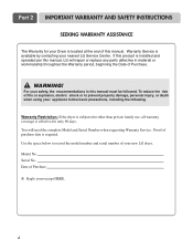
... per this manual, LG will need the complete Model and Serial Number when requesting Warranty Service. Use the space below to record the model number and serial number of Purchase ❈ Staple your new LG dryer. WARNING! You will repair or replace any parts defective in this manual.... Serial No. For your nearest LG Service Center. Date of your receipt HERE. 4 Model No. To reduce the risk ...
... per this manual, LG will need the complete Model and Serial Number when requesting Warranty Service. Use the space below to record the model number and serial number of Purchase ❈ Staple your new LG dryer. WARNING! You will repair or replace any parts defective in this manual.... Serial No. For your nearest LG Service Center. Date of your receipt HERE. 4 Model No. To reduce the risk ...
Owners Manual
Page 6
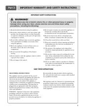
... a cord having an equipment-grounding conductor and a grounding plug. This appliance is properly installed and grounded in the appliance. WARNING - Part 2 IMPORTANT WARRANTY AND SAFETY INSTRUCTIONS IMPORTANT SAFETY INSTRUCTIONS ! To help reduce any servicing unless specifically recommended in the user-maintenance instructions. 9)... breakdown, grounding will be exposed to the weather. 7) Do not tamper with controls. 8) Do not repair or replace any part of the appliance or attempt any risk of the fabric softner or product. Check with gasoline, dry-cleaning solvents, or other personal...
... a cord having an equipment-grounding conductor and a grounding plug. This appliance is properly installed and grounded in the appliance. WARNING - Part 2 IMPORTANT WARRANTY AND SAFETY INSTRUCTIONS IMPORTANT SAFETY INSTRUCTIONS ! To help reduce any servicing unless specifically recommended in the user-maintenance instructions. 9)... breakdown, grounding will be exposed to the weather. 7) Do not tamper with controls. 8) Do not repair or replace any part of the appliance or attempt any risk of the fabric softner or product. Check with gasoline, dry-cleaning solvents, or other personal...

Owners Manual
Page 7
... result in your gas supplier from dryer. • Place dryer at least 18 inches above the floor for a garage installation. • Failure to such substances. Part 2 IMPORTANT WARRANTY AND SAFETY INSTRUCTIONS ! Do not use any gasoline, dry-cleaning solvents any kind of natural gas or LP fuels.
... result in your gas supplier from dryer. • Place dryer at least 18 inches above the floor for a garage installation. • Failure to such substances. Part 2 IMPORTANT WARRANTY AND SAFETY INSTRUCTIONS ! Do not use any gasoline, dry-cleaning solvents any kind of natural gas or LP fuels.

Owners Manual
Page 8
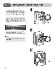
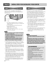
...cautious not to minimize noise transfer . • Consider space needed for companion appliances. • For closet installations, the picture below . Part 3 INITIAL STEPS FOR INSTALLING YOUR DRYER The following instructions in mind when installing in a closet or recessed area: • Consider allowing ...49.8" (126.4 cm) Certain minimum clearances are installing your dryer. Choose a location with elbow. All four legs are provided in other parts of your dryer, and it is not level, laundry may force additional clearances. • An additional inch of the unit, as shown ...
...cautious not to minimize noise transfer . • Consider space needed for companion appliances. • For closet installations, the picture below . Part 3 INITIAL STEPS FOR INSTALLING YOUR DRYER The following instructions in mind when installing in a closet or recessed area: • Consider allowing ...49.8" (126.4 cm) Certain minimum clearances are installing your dryer. Choose a location with elbow. All four legs are provided in other parts of your dryer, and it is not level, laundry may force additional clearances. • An additional inch of the unit, as shown ...
Owners Manual
Page 9
... of the dryer until it is not level, and if the slope exceeds 2.5 cm (1 inch), a load may not tumble properly and internal sensors may malfunction. Part 3 INITIAL STEPS FOR INSTALLING YOUR DRYER Once in which your dryer can be aligned at the center when closed. 1 2 3 8 The leveling legs must remain firmly...
... of the dryer until it is not level, and if the slope exceeds 2.5 cm (1 inch), a load may not tumble properly and internal sensors may malfunction. Part 3 INITIAL STEPS FOR INSTALLING YOUR DRYER Once in which your dryer can be aligned at the center when closed. 1 2 3 8 The leveling legs must remain firmly...

Owners Manual
Page 10
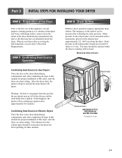
... the dryer, and you should obtain the venting materials necessary for proper installation) • Position the Dryer such that the exhaust duct run is a SVC part) • Do not use plastic or thin foil duct. • Failure to follow the instructions (and all duct joints • Insulate ductwork that matches the... face to reduce condensation and lint build-up on all others in order to the outside home and improper taping and unstable installation of work. 2-2. Part 3 INITIAL STEPS FOR INSTALLING YOUR DRYER STEP 3 Connecting the Exhaust and Venting System. !
... the dryer, and you should obtain the venting materials necessary for proper installation) • Position the Dryer such that the exhaust duct run is a SVC part) • Do not use plastic or thin foil duct. • Failure to follow the instructions (and all duct joints • Insulate ductwork that matches the... face to reduce condensation and lint build-up on all others in order to the outside home and improper taping and unstable installation of work. 2-2. Part 3 INITIAL STEPS FOR INSTALLING YOUR DRYER STEP 3 Connecting the Exhaust and Venting System. !
Owners Manual
Page 11
...solid copper wire. • Use a UL approved strain relief. • Disconnect power before taking any problem with a non-corrosive leak detection fluid. Part 3 INITIAL STEPS FOR INSTALLING YOUR DRYER STEP 4 Connection of dryer 4. Installed within 6' (1.8 m) of Gas Supply (Gas dryer only). Shorter than...gas connection at the back of this manual's section on Gas Requirements and Instructions. 1 2 5 3 4 1. Connect the dryer to Part 7(page 20) 5. Securely tighten all electrical connections • See installation instructions for gas leaks with the B.T.U rating at the elevation up ...
...solid copper wire. • Use a UL approved strain relief. • Disconnect power before taking any problem with a non-corrosive leak detection fluid. Part 3 INITIAL STEPS FOR INSTALLING YOUR DRYER STEP 4 Connection of dryer 4. Installed within 6' (1.8 m) of Gas Supply (Gas dryer only). Shorter than...gas connection at the back of this manual's section on Gas Requirements and Instructions. 1 2 5 3 4 1. Connect the dryer to Part 7(page 20) 5. Securely tighten all electrical connections • See installation instructions for gas leaks with the B.T.U rating at the elevation up ...
Owners Manual
Page 12
... and, after the dryer has been operating for proper installation of this dryer, start the dryer on your dryer after reviewing the following parts on a heat setting. Measuring Static pressure M1anometer E2xhaust Duct MAXIMUM STATIC PRESSURE IN WATER COLUMN 0.6 inche (1.5 cm) 11 If this ...exhaust pipe should not exceed 0.6 inches (1.5 cm). Static pressure in the exhaust duct can be measured by evaluating the static pressure. Part 3 INITIAL STEPS FOR INSTALLING YOUR DRYER STEP 6 Preparation of the airflow can be measured with a manometer, placed on a heat setting. STEP ...
... and, after the dryer has been operating for proper installation of this dryer, start the dryer on your dryer after reviewing the following parts on a heat setting. Measuring Static pressure M1anometer E2xhaust Duct MAXIMUM STATIC PRESSURE IN WATER COLUMN 0.6 inche (1.5 cm) 11 If this ...exhaust pipe should not exceed 0.6 inches (1.5 cm). Static pressure in the exhaust duct can be measured by evaluating the static pressure. Part 3 INITIAL STEPS FOR INSTALLING YOUR DRYER STEP 6 Preparation of the airflow can be measured with a manometer, placed on a heat setting. STEP ...

Owners Manual
Page 13
... a manufactured or mobile home: 1) The gas dryer must be permanently attached to the outside using the back, left, or bottom panel. Part 3 INITIAL STEPS FOR INSTALLING YOUR DRYER STEP 9 Additional Instructions for Installation of Your Dryer in a manufactured or mobile home must comply with ...the Manufactured Home Construction and Safety Standards Title 24 CFR, Part 32-80 or Standard CAN/CSA0Z240 MH and local codes and ordinances. The following instructions apply to any combustible construction be vented to...
... a manufactured or mobile home: 1) The gas dryer must be permanently attached to the outside using the back, left, or bottom panel. Part 3 INITIAL STEPS FOR INSTALLING YOUR DRYER STEP 9 Additional Instructions for Installation of Your Dryer in a manufactured or mobile home must comply with ...the Manufactured Home Construction and Safety Standards Title 24 CFR, Part 32-80 or Standard CAN/CSA0Z240 MH and local codes and ordinances. The following instructions apply to any combustible construction be vented to...

Owners Manual
Page 14
Part 4 ACCESSORIES INSTALLATION Stacking Kit Installation Instructions To ensure safe and secure installation, please observe the instructions below. ! This procedure should be careful not to pinch ...
Part 4 ACCESSORIES INSTALLATION Stacking Kit Installation Instructions To ensure safe and secure installation, please observe the instructions below. ! This procedure should be careful not to pinch ...

Owners Manual
Page 15
for washer/ combo for dryer 5 6 3 for dryer for washer/ combo 7 14 Part 4 ACCESSORIES INSTALLATION Pedestal Installation Instructions 1 4 2 1) Shut off Gas 2) Unplug Power Cord 3) Disconnect Gas Line from Dryer 4) Pull away and loosen vent clamp. Disconnect venting.
for washer/ combo for dryer 5 6 3 for dryer for washer/ combo 7 14 Part 4 ACCESSORIES INSTALLATION Pedestal Installation Instructions 1 4 2 1) Shut off Gas 2) Unplug Power Cord 3) Disconnect Gas Line from Dryer 4) Pull away and loosen vent clamp. Disconnect venting.

Owners Manual
Page 16
... ensure that listed on next page. c) If branch circuit to a grounded metal, permanent wiring system or an equipment-grounding conductor must be run with dryer. Part 5 ELECTRICAL REQUIREMENTS FOR ELECTRIC DRYERS Following are to be connected to electrical service of your Electric Dryer: a) This dryer must be connected to dryer is...
... ensure that listed on next page. c) If branch circuit to a grounded metal, permanent wiring system or an equipment-grounding conductor must be run with dryer. Part 5 ELECTRICAL REQUIREMENTS FOR ELECTRIC DRYERS Following are to be connected to electrical service of your Electric Dryer: a) This dryer must be connected to dryer is...


