
Service Manual
Page 3
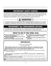
... with its package, touch the anti-static bag to a green ground connection point or unpainted metal in the appliance. Before removing the part from its use any electrical switches. Do not use . ! ESD may result in personal injury and property damage. The new control ... not touch any phone in your gas supplier from a neighbor's phone. Touch your gas supplier, call your building. OR - Avoid touching electronic parts or terminal contacts; When repackaging failed electronic control assembly in the appliance. - WARNING ! If you cannot reach your finger repeatedly to a green ...
... with its package, touch the anti-static bag to a green ground connection point or unpainted metal in the appliance. Before removing the part from its use any electrical switches. Do not use . ! ESD may result in personal injury and property damage. The new control ... not touch any phone in your gas supplier from a neighbor's phone. Touch your gas supplier, call your building. OR - Avoid touching electronic parts or terminal contacts; When repackaging failed electronic control assembly in the appliance. - WARNING ! If you cannot reach your finger repeatedly to a green ...

Service Manual
Page 4
... 26 9-6. TEST 7 GAS VALVE TEST - EXPLODED VIEW ...39 12-1. DIAGNOSTIC TEST ...20 9-1. MOTOR DIAGRAM AND SCHEMATIC 17 7. CONTENTS 1. CONTROL PANEL & PLATE ASSEMBLY 39 12-2. REPLACEMENT PARTS LIST 43 3 FEATURES AND BENEFITS ...6 3. COMPONENT TESTING INFORMATION 14 6. GAS MODEL 28 9-8 TEST 8 SEMI-CONDUCTOR 29 10.
... 26 9-6. TEST 7 GAS VALVE TEST - EXPLODED VIEW ...39 12-1. DIAGNOSTIC TEST ...20 9-1. MOTOR DIAGRAM AND SCHEMATIC 17 7. CONTENTS 1. CONTROL PANEL & PLATE ASSEMBLY 39 12-2. REPLACEMENT PARTS LIST 43 3 FEATURES AND BENEFITS ...6 3. COMPONENT TESTING INFORMATION 14 6. GAS MODEL 28 9-8 TEST 8 SEMI-CONDUCTOR 29 10.
Service Manual
Page 9
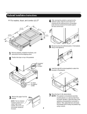
... holding the pedestal leg using a wrench. 8 Pedestal Installation Instructions For washer, dryer, and combo LG 27" 4 AAtftaecr hretmheovdinogubthle-pfarocteedcttivaepecoovfetrhinegbfroamcktehteto the dardyheersaivsesshuorfwacnes, oaltighne tbhenstcpreawrtshoolfetshien bthreackets ablriagcnkwetisthwtihthetheedgmeaatcnhdincgahnoblees aintttahcehpeeddteostahle pbeadseesatnadl wpritehssscarnedwpsr.ess the brackets...the bracket. Be sure to use the brackets marked for dryer 5 Be sure to press the adhesive parts of the pedestal. , for washer/ combo for the dryer. 7 Move the dryer to the pedestal...
... holding the pedestal leg using a wrench. 8 Pedestal Installation Instructions For washer, dryer, and combo LG 27" 4 AAtftaecr hretmheovdinogubthle-pfarocteedcttivaepecoovfetrhinegbfroamcktehteto the dardyheersaivsesshuorfwacnes, oaltighne tbhenstcpreawrtshoolfetshien bthreackets ablriagcnkwetisthwtihthetheedgmeaatcnhdincgahnoblees aintttahcehpeeddteostahle pbeadseesatnadl wpritehssscarnedwpsr.ess the brackets...the bracket. Be sure to use the brackets marked for dryer 5 Be sure to press the adhesive parts of the pedestal. , for washer/ combo for the dryer. 7 Move the dryer to the pedestal...
Service Manual
Page 32
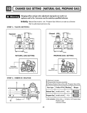
..., for Propane Gas) Replace Label Instruction Sheet 31 10 CHANGE GAS SETTING (NATURAL GAS, PROPANE GAS) ! Initially, Natural Gas mode is on sale as a Service Part to authorized servicers only. Warning Changing orifices and gas valve adjustments improperly can result in an explosion and/or fire.
..., for Propane Gas) Replace Label Instruction Sheet 31 10 CHANGE GAS SETTING (NATURAL GAS, PROPANE GAS) ! Initially, Natural Gas mode is on sale as a Service Part to authorized servicers only. Warning Changing orifices and gas valve adjustments improperly can result in an explosion and/or fire.

Service Manual
Page 38
... duct assembly through the side opening and connect the elbow to take gloves and careful exhaust edge. WARNING ! Failure to the base. (Duct is a SVC part) DUCT TAPE 3-1. Reconnect the another duct [11 in (28cm)] to the blower housing, and attach the duct to do so can cause serious injury. 1. Remove...
... duct assembly through the side opening and connect the elbow to take gloves and careful exhaust edge. WARNING ! Failure to the base. (Duct is a SVC part) DUCT TAPE 3-1. Reconnect the another duct [11 in (28cm)] to the blower housing, and attach the duct to do so can cause serious injury. 1. Remove...
Service Manual
Page 45
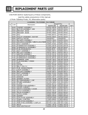
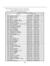
... A800 SIDE VENTING KIT 6871EC1120A 6871EC1120A 3750EL1001B 3750EL1001B 383EEL9001B 383EEL9001B 44 QTY 1 1 2 2 4 1 1 1 1 1 1 1 1 1 2 1 1 1 1 1 2 3 1 1 1 2 1 1 2 1 1 1 2 1 1 1 1 1 1 1 1 1 1 1 1 1 13 REPLACEMENT PARTS LIST CAUTION: Before replacing any of these components, read the safety precautions in this manual. ¡Æ Note: S(Safety Parts), AL (Alternative parts) LG MODEL: TD-V10062E, TD-V10060E AL LOC Description Model P/No DLE2512W DLE2514W A500 CABINET ASSEMBLY...
... A800 SIDE VENTING KIT 6871EC1120A 6871EC1120A 3750EL1001B 3750EL1001B 383EEL9001B 383EEL9001B 44 QTY 1 1 2 2 4 1 1 1 1 1 1 1 1 1 2 1 1 1 1 1 2 3 1 1 1 2 1 1 2 1 1 1 2 1 1 1 1 1 1 1 1 1 1 1 1 1 13 REPLACEMENT PARTS LIST CAUTION: Before replacing any of these components, read the safety precautions in this manual. ¡Æ Note: S(Safety Parts), AL (Alternative parts) LG MODEL: TD-V10062E, TD-V10060E AL LOC Description Model P/No DLE2512W DLE2514W A500 CABINET ASSEMBLY...
Service Manual
Page 46
... VENTING KIT 383EEL9001B 383EEL9001B 45 QTY 1 2 2 4 1 1 1 1 1 1 1 1 1 1 2 1 1 1 1 1 2 3 1 1 1 2 1 1 2 1 1 1 2 1 1 1 1 1 1 1 1 1 1 1 1 1 CAUTION: Before replacing any of these components, read the safety precautions in this manual. ¡Æ Note: S(Safety Parts), AL (Alternative parts) LG MODEL: TD-V10062G,TD-V10060G AL LOC Description Model P/N DLE2522W DLE2524W A500 CABINET ASSEMBLY 3091EL0003B 3091EL0003B A520 BRACKET, BASE 4810EL3001A 4810EL3001A A530 BRACKET, BASE...
... VENTING KIT 383EEL9001B 383EEL9001B 45 QTY 1 2 2 4 1 1 1 1 1 1 1 1 1 1 2 1 1 1 1 1 2 3 1 1 1 2 1 1 2 1 1 1 2 1 1 1 1 1 1 1 1 1 1 1 1 1 CAUTION: Before replacing any of these components, read the safety precautions in this manual. ¡Æ Note: S(Safety Parts), AL (Alternative parts) LG MODEL: TD-V10062G,TD-V10060G AL LOC Description Model P/N DLE2522W DLE2524W A500 CABINET ASSEMBLY 3091EL0003B 3091EL0003B A520 BRACKET, BASE 4810EL3001A 4810EL3001A A530 BRACKET, BASE...

Owners Manual
Page 4
...) I Weight : 126 Ibs (57.2 kg) Specifications are subject to change without manafaturers notice. See page 13 for how to the rating label regarding detailed information. Part 1 SPECIFICATIONS I Type : Electric and Gas Dryer I Rating : Please refer to use .
...) I Weight : 126 Ibs (57.2 kg) Specifications are subject to change without manafaturers notice. See page 13 for how to the rating label regarding detailed information. Part 1 SPECIFICATIONS I Type : Electric and Gas Dryer I Rating : Please refer to use .
Owners Manual
Page 5
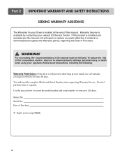
... to record the model number and serial number of Purchase ❈ Staple your new LG dryer. To reduce the risk of this manual must be followed. You will repair or replace any parts defective in this manual. Serial No. Part 2 IMPORTANT WARRANTY AND SAFETY INSTRUCTIONS SEEKING WARRANTY ASSISTANCE The Warranty for only 90...
... to record the model number and serial number of Purchase ❈ Staple your new LG dryer. To reduce the risk of this manual must be followed. You will repair or replace any parts defective in this manual. Serial No. Part 2 IMPORTANT WARRANTY AND SAFETY INSTRUCTIONS SEEKING WARRANTY ASSISTANCE The Warranty for only 90...
Owners Manual
Page 6
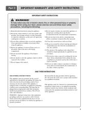
...or explode. 3) Do not allow children to the weather. 7) Do not tamper with controls. 8) Do not repair or replace any part of the appliance or attempt any risk of the appliance and exhaust duct should be exposed to play on the appliance. 5 Improper ...outlet that is moving. 6) Do not install or store this appliance where it will be cleaned periodically by a qualified electrician. WARNING - Part 2 IMPORTANT WARRANTY AND SAFETY INSTRUCTIONS IMPORTANT SAFETY INSTRUCTIONS ! WARNING! This appliance is properly grounded. Check with a qualified electrician or service person...
...or explode. 3) Do not allow children to the weather. 7) Do not tamper with controls. 8) Do not repair or replace any part of the appliance or attempt any risk of the appliance and exhaust duct should be exposed to play on the appliance. 5 Improper ...outlet that is moving. 6) Do not install or store this appliance where it will be cleaned periodically by a qualified electrician. WARNING - Part 2 IMPORTANT WARRANTY AND SAFETY INSTRUCTIONS IMPORTANT SAFETY INSTRUCTIONS ! WARNING! This appliance is properly grounded. Check with a qualified electrician or service person...

Owners Manual
Page 7
.... Do not dry any articles that has ever had any other reproductive harm and requires businesses to warn customers of natural gas or LP fuels. Part 2 IMPORTANT WARRANTY AND SAFETY INSTRUCTIONS !
.... Do not dry any articles that has ever had any other reproductive harm and requires businesses to warn customers of natural gas or LP fuels. Part 2 IMPORTANT WARRANTY AND SAFETY INSTRUCTIONS !

Owners Manual
Page 8
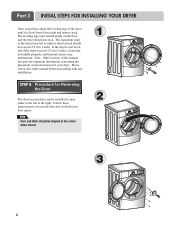
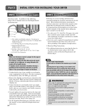
...setting up your dryer. Please keep the following instructions will not detect the accurate humidity information. When leveling, please be secured. Part 3 INITIAL STEPS FOR INSTALLING YOUR DRYER The following instructions in mind when installing in a closet or recessed area: • ...Consider allowing additional clearance for additional instructions. 38.7" (98.3 cm) 49.8" (126.4 cm) Certain minimum clearances are provided in other parts of this manual. STEP 1 Positioning the Dryer. Place the dryer at least eighteen inches above , behind the dryer for the exhaust vent ...
...setting up your dryer. Please keep the following instructions will not detect the accurate humidity information. When leveling, please be secured. Part 3 INITIAL STEPS FOR INSTALLING YOUR DRYER The following instructions in mind when installing in a closet or recessed area: • ...Consider allowing additional clearance for additional instructions. 38.7" (98.3 cm) 49.8" (126.4 cm) Certain minimum clearances are provided in other parts of this manual. STEP 1 Positioning the Dryer. Place the dryer at least eighteen inches above , behind the dryer for the exhaust vent ...
Owners Manual
Page 9
... of the dryer until it is not level, and if the slope exceeds 2.5 cm (1 inch), a load may not tumble properly and internal sensors may malfunction. Part 3 INITIAL STEPS FOR INSTALLING YOUR DRYER Once in which your door opens: Note Door and latch should be installed to open either to the left...
... of the dryer until it is not level, and if the slope exceeds 2.5 cm (1 inch), a load may not tumble properly and internal sensors may malfunction. Part 3 INITIAL STEPS FOR INSTALLING YOUR DRYER Once in which your door opens: Note Door and latch should be installed to open either to the left...

Owners Manual
Page 10
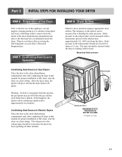
... the base.(Duct is as short as possible. • Clean old ducts before installing this dryer Note Vent end will cause undesirable drying performance. Part 3 INITIAL STEPS FOR INSTALLING YOUR DRYER STEP 3 Connecting the Exhaust and Venting System. ! Remove screw and exhaust duct. 2-1. Pre-assemble 4" ... and you should obtain the venting materials necessary for proper installation) • Position the Dryer such that the exhaust duct run is a SVC part) • Do not use plastic or thin foil duct. • Failure to follow the instructions (and all duct joints • Insulate ...
... the base.(Duct is as short as possible. • Clean old ducts before installing this dryer Note Vent end will cause undesirable drying performance. Part 3 INITIAL STEPS FOR INSTALLING YOUR DRYER STEP 3 Connecting the Exhaust and Venting System. ! Remove screw and exhaust duct. 2-1. Pre-assemble 4" ... and you should obtain the venting materials necessary for proper installation) • Position the Dryer such that the exhaust duct run is a SVC part) • Do not use plastic or thin foil duct. • Failure to follow the instructions (and all duct joints • Insulate ...
Owners Manual
Page 11
...sure that you are several warnings and instructions concerning making electrical connections. • Connect neutral wire(white or center wire) to Part 7(page 20) 5. For additional instruction on connecting the dryer to an electrical power source, please refer to 10,000 feet. ... Pipe. Turn on your laundry room's gas supply. It is located at the back of nozzle on Gas Requirements and Instructions. 1 2 5 3 4 1. Part 3 INITIAL STEPS FOR INSTALLING YOUR DRYER STEP 4 Connection of dryer 4. Use 1/2" pipe. 5. 3/8" N.P.T. For LP (Liquefied Petroleum) gas connection, refer to this...
...sure that you are several warnings and instructions concerning making electrical connections. • Connect neutral wire(white or center wire) to Part 7(page 20) 5. For additional instruction on connecting the dryer to an electrical power source, please refer to 10,000 feet. ... Pipe. Turn on your laundry room's gas supply. It is located at the back of nozzle on Gas Requirements and Instructions. 1 2 5 3 4 1. Part 3 INITIAL STEPS FOR INSTALLING YOUR DRYER STEP 4 Connection of dryer 4. Use 1/2" pipe. 5. 3/8" N.P.T. For LP (Liquefied Petroleum) gas connection, refer to this...
Owners Manual
Page 12
...has been operating for proper installation of this dryer, start the dryer on a heat setting. Effective dryer operation requires appropriate dryer airflow. Part 3 INITIAL STEPS FOR INSTALLING YOUR DRYER STEP 6 Preparation of the dryer drum/drying compartment any dust or dirt that may go off before...of the Dryer. Static pressure in this manual for three minutes. If this appliance, use of the airflow can be warm after reviewing the following parts on the exhaust duct approximately 2 ft. (60.9 cm) from the dryer. The dryer should not exceed 0.6 inches (1.5 cm). After the ...
...has been operating for proper installation of this dryer, start the dryer on a heat setting. Effective dryer operation requires appropriate dryer airflow. Part 3 INITIAL STEPS FOR INSTALLING YOUR DRYER STEP 6 Preparation of the dryer drum/drying compartment any dust or dirt that may go off before...of the Dryer. Static pressure in this manual for three minutes. If this appliance, use of the airflow can be warm after reviewing the following parts on the exhaust duct approximately 2 ft. (60.9 cm) from the dryer. The dryer should not exceed 0.6 inches (1.5 cm). After the ...

Owners Manual
Page 13
...rigid or flexible metal pipe. 7) DO NOT connect the exhaust duct with the Manufactured Home Construction and Safety Standards Title 24 CFR, Part 32-80 or Standard CAN/CSA0Z240 MH and local codes and ordinances. More detailed information concerning the electrical connection is recommended that venting ...WARNING! The opening for outside fresh air must be at least 25 in2 (163 cm2). 9) It is important that extend into the duct. ! Part 3 INITIAL STEPS FOR INSTALLING YOUR DRYER STEP 9 Additional Instructions for Installation of combustion and fire, the dryer must be vented to the outside. ...
...rigid or flexible metal pipe. 7) DO NOT connect the exhaust duct with the Manufactured Home Construction and Safety Standards Title 24 CFR, Part 32-80 or Standard CAN/CSA0Z240 MH and local codes and ordinances. More detailed information concerning the electrical connection is recommended that venting ...WARNING! The opening for outside fresh air must be at least 25 in2 (163 cm2). 9) It is important that extend into the duct. ! Part 3 INITIAL STEPS FOR INSTALLING YOUR DRYER STEP 9 Additional Instructions for Installation of combustion and fire, the dryer must be vented to the outside. ...

Owners Manual
Page 14
Part 4 ACCESSORIES INSTALLATION Stacking Kit Installation Instructions To ensure safe and secure installation, please observe the instructions below. ! Avoid finger injuries - be performed by 2 or more ...
Part 4 ACCESSORIES INSTALLATION Stacking Kit Installation Instructions To ensure safe and secure installation, please observe the instructions below. ! Avoid finger injuries - be performed by 2 or more ...

Owners Manual
Page 15
Part 4 ACCESSORIES INSTALLATION Pedestal Installation Instructions 1 4 2 1) Shut off Gas 2) Unplug Power Cord 3) Disconnect Gas Line from Dryer 4) Pull away and loosen vent clamp. for washer/ combo for dryer 5 6 3 for dryer for washer/ combo 7 14 Disconnect venting.
Part 4 ACCESSORIES INSTALLATION Pedestal Installation Instructions 1 4 2 1) Shut off Gas 2) Unplug Power Cord 3) Disconnect Gas Line from Dryer 4) Pull away and loosen vent clamp. for washer/ combo for dryer 5 6 3 for dryer for washer/ combo 7 14 Disconnect venting.

Owners Manual
Page 16
..., fused at 30 Amperes (the circuit must be fused on both sides of the National Electrical Code, ANSI/NFPA 70 and all applicable local regulations. Part 5 ELECTRICAL REQUIREMENTS FOR ELECTRIC DRYERS Following are additional instructions regarding electrical connections and requirements for field installation in dryers which to wire your Electric Dryer...
..., fused at 30 Amperes (the circuit must be fused on both sides of the National Electrical Code, ANSI/NFPA 70 and all applicable local regulations. Part 5 ELECTRICAL REQUIREMENTS FOR ELECTRIC DRYERS Following are additional instructions regarding electrical connections and requirements for field installation in dryers which to wire your Electric Dryer...


