
Service Manual
Page 16
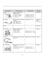
Gas valve valve 1 Measure resistance of terminal to terminal Resistance value: 100~800Ω • Gas type 12. Component 7. Igniter valve 2 Measure resistance of the following terminal Terminal: 1 (COM) - 2 Terminal: 1 (COM) - 3 Terminal: 2 - 3 Check result Resistance value: 10Ω Resistance value: 10Ω Resistance value: 20&#...
Gas valve valve 1 Measure resistance of terminal to terminal Resistance value: 100~800Ω • Gas type 12. Component 7. Igniter valve 2 Measure resistance of the following terminal Terminal: 1 (COM) - 2 Terminal: 1 (COM) - 3 Terminal: 2 - 3 Check result Resistance value: 10Ω Resistance value: 10Ω Resistance value: 20&#...
Service Manual
Page 20
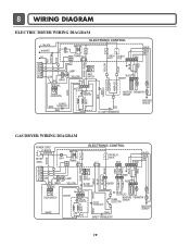
... PLC MODEM WHITE 34 3 1 1 3 123 6 5 4321 8 7 6 5 4 3 2 COM 1 NO 1 2 GRAY NC LAMP YELLOW BROWN BROWN 1 2 3 BELT SWITCH BLOWER THERMOSTAT GRAY BLUE BLUE BLUE RED 23 1212 IGNITER BLUE 21 21 YELLOW 123 DOOR SWITCH MOTOR 2379 OVERLOAD PROTECTOR HI-LIMIT THERMOSTAT WHITE DC VALVE1 DC VALVE2 MOISTURE THERMISTOR FLAME SENSOR DETECTOR MOISTURE...
... PLC MODEM WHITE 34 3 1 1 3 123 6 5 4321 8 7 6 5 4 3 2 COM 1 NO 1 2 GRAY NC LAMP YELLOW BROWN BROWN 1 2 3 BELT SWITCH BLOWER THERMOSTAT GRAY BLUE BLUE BLUE RED 23 1212 IGNITER BLUE 21 21 YELLOW 123 DOOR SWITCH MOTOR 2379 OVERLOAD PROTECTOR HI-LIMIT THERMOSTAT WHITE DC VALVE1 DC VALVE2 MOISTURE THERMISTOR FLAME SENSOR DETECTOR MOISTURE...

Service Manual
Page 30
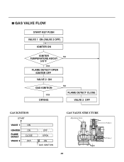
...gloves, to avoid electric shock. Measurement Condition With dryer power on Valve 1 Igniter Valve 2 Power On & Start (Normal Cycle) NO When measuring Valve 1 voltage, More than DC 90V? (10 sec after Igniter off) YES NO • Check Gas connection or Gas supply When measuring terminal... Valve 2, Valves are Off? Drying time takes longer. Trouble Symptom While operating, Heating will not work. YES NO • Check thermostat Hi limit Safety Igniter operates? (after Off ) NO • Change Valve If "Valve 1 " and "Valve 2" are under DC 10V, Valves are more than DC 90V...
...gloves, to avoid electric shock. Measurement Condition With dryer power on Valve 1 Igniter Valve 2 Power On & Start (Normal Cycle) NO When measuring Valve 1 voltage, More than DC 90V? (10 sec after Igniter off) YES NO • Check Gas connection or Gas supply When measuring terminal... Valve 2, Valves are Off? Drying time takes longer. Trouble Symptom While operating, Heating will not work. YES NO • Check thermostat Hi limit Safety Igniter operates? (after Off ) NO • Change Valve If "Valve 1 " and "Valve 2" are under DC 10V, Valves are more than DC 90V...
Service Manual
Page 33
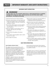
GAS VALVE FLOW START KEY PUSH VALVE 1 ON (VALVE 2 OFF) IGNITER ON IGNITER NO TEMPERATURE ABOUT 370°F YES FLAME DETECT OPEN IGNITER OFF VALVE 2 ON GAS IGNITION YES DRYING NO FLAME DETECT CLOSE VALVE 2 OFF GAS IGNITION START VALVE 1 IGNITER FLAME DETECT VALVE 2 ON ON CLOSE OFF OFF OPEN ON GAS IGNITION GAS VALVE STRUCTURE Adjustment Screw 32
GAS VALVE FLOW START KEY PUSH VALVE 1 ON (VALVE 2 OFF) IGNITER ON IGNITER NO TEMPERATURE ABOUT 370°F YES FLAME DETECT OPEN IGNITER OFF VALVE 2 ON GAS IGNITION YES DRYING NO FLAME DETECT CLOSE VALVE 2 OFF GAS IGNITION START VALVE 1 IGNITER FLAME DETECT VALVE 2 ON ON CLOSE OFF OFF OPEN ON GAS IGNITION GAS VALVE STRUCTURE Adjustment Screw 32
Owners Manual
Page 6
... event of malfunction or breakdown, grounding will not fit the outlet, have come into contact with cooking oils may contribute to a chemical reaction that could ignite or explode. 3) Do not allow children to the equipment-grounding terminal or lead on or in a risk of least resistance for electric current. The plug...
... event of malfunction or breakdown, grounding will not fit the outlet, have come into contact with cooking oils may contribute to a chemical reaction that could ignite or explode. 3) Do not allow children to the equipment-grounding terminal or lead on or in a risk of least resistance for electric current. The plug...
Owners Manual
Page 11
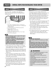
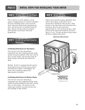
... 1/2" pipe. 5. 3/8" N.P.T. Four-wire cord is located at this appliance through neutral. 3. Adjusting burner input setting is appropriate for gas leaks with LNG nozzle will not ignite burner. WARNING! • Use a new UL approved 30 amp power supply cord or 10 gauge solid copper wire. • Use a UL approved strain relief. •...
... 1/2" pipe. 5. 3/8" N.P.T. Four-wire cord is located at this appliance through neutral. 3. Adjusting burner input setting is appropriate for gas leaks with LNG nozzle will not ignite burner. WARNING! • Use a new UL approved 30 amp power supply cord or 10 gauge solid copper wire. • Use a UL approved strain relief. •...
Owners Manual
Page 12
... E2xhaust Duct MAXIMUM STATIC PRESSURE IN WATER COLUMN 0.6 inche (1.5 cm) 11 After the dryer starts, the igniter will glow red and the main burner will re-attempt gas ignition after completing all air is running with no load. Warning: If all steps in your dryer's Electrical Requirements... gas and the main burner have accumulated inside of this happens, the igniter will ignite. Confirming Heat Source in Electric Dryers Close the door to remove from the gas line, the gas igniter may have ignited. Static pressure in the exhaust duct can be measured with damp cloth ...
... E2xhaust Duct MAXIMUM STATIC PRESSURE IN WATER COLUMN 0.6 inche (1.5 cm) 11 After the dryer starts, the igniter will glow red and the main burner will re-attempt gas ignition after completing all air is running with no load. Warning: If all steps in your dryer's Electrical Requirements... gas and the main burner have accumulated inside of this happens, the igniter will ignite. Confirming Heat Source in Electric Dryers Close the door to remove from the gas line, the gas igniter may have ignited. Static pressure in the exhaust duct can be measured with damp cloth ...


