
Owner's Manual
Page 12
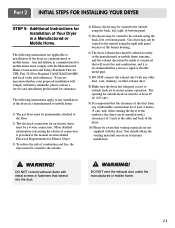
... pipe. 7) DO NOT connect the exhaust duct with these standards, please contact a service and installation professional for outside using the right side panel because of the dryer in a manufactured or mobile home must be made of a material that will comply with any combustible construction be at ...will resist fire and combustion, and it is recommended that venting materials are applicable to outside using the back, left , or bottom panel. DO NOT vent the exhaust duct under the manufactured or mobile home. 11 You should obtain the venting materials necessary for Installation ...
... pipe. 7) DO NOT connect the exhaust duct with these standards, please contact a service and installation professional for outside using the right side panel because of the dryer in a manufactured or mobile home must be made of a material that will comply with any combustible construction be at ...will resist fire and combustion, and it is recommended that venting materials are applicable to outside using the back, left , or bottom panel. DO NOT vent the exhaust duct under the manufactured or mobile home. 11 You should obtain the venting materials necessary for Installation ...
Owner's Manual
Page 15
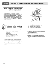
... the connection of a frame-grounding conductor to the neutral wire, use these instructions. If your local codes or ordinances permit the connection of dryer rear panel. Center silver-colored terminal block screw d. Tighten strain relief screws. 5.
... the connection of a frame-grounding conductor to the neutral wire, use these instructions. If your local codes or ordinances permit the connection of dryer rear panel. Center silver-colored terminal block screw d. Tighten strain relief screws. 5.
Owner's Manual
Page 16
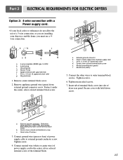
... appliance ground wire (green) from external ground connector screw. Secure cover with upturned ends f. 3/4 in . (1.9 cm) UL-listed strain relief d. Green wire of dryer rear panel. Connect the other wires to external ground conductor screw. Center silver-colored terminal block screw e. Dotted line shows position of the terminal block. 15 Center...
... appliance ground wire (green) from external ground connector screw. Secure cover with upturned ends f. 3/4 in . (1.9 cm) UL-listed strain relief d. Green wire of dryer rear panel. Connect the other wires to external ground conductor screw. Center silver-colored terminal block screw e. Dotted line shows position of the terminal block. 15 Center...
Owner's Manual
Page 17
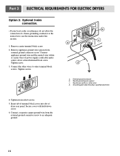
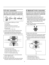
... cord/cable under this section. 1. Tighten screw. 3. External ground connector b. Neutral grounding wire (green) c. Insert tab of terminal block cover into slot of dryer rear panel. Part 3 ELECTRICAL REQUIREMENTS FOR ELECTRIC DRYERS Option 3: Optional 3-wire connection. • If your local codes or ordinances do not allow the connection of a frame-grounding...
... cord/cable under this section. 1. Tighten screw. 3. External ground connector b. Neutral grounding wire (green) c. Insert tab of terminal block cover into slot of dryer rear panel. Part 3 ELECTRICAL REQUIREMENTS FOR ELECTRIC DRYERS Option 3: Optional 3-wire connection. • If your local codes or ordinances do not allow the connection of a frame-grounding...
Owner's Manual
Page 21
... Cleaning the Lint Screen 1. The lint filter can build up , and help ensure proper operation of the control panel. 9. Disconnect the dryer's electric power prior to become congested more frequently. Clean the control panel with hot or warm water. Wipe the exterior of synthetic fibers and natural fibers), causing the lint screen...
... Cleaning the Lint Screen 1. The lint filter can build up , and help ensure proper operation of the control panel. 9. Disconnect the dryer's electric power prior to become congested more frequently. Clean the control panel with hot or warm water. Wipe the exterior of synthetic fibers and natural fibers), causing the lint screen...
Owner's Manual
Page 27
..., and NORMAL cycles. Allow space around items for Rack Drying Setting Time* (Minutes) Washable wool items (block to shape and lay flat on the control panel and the termination of the rack. The ANTI BACTERIAL process produces high temperature during the cycle. Rest the rack on the rack. Make sure items...
..., and NORMAL cycles. Allow space around items for Rack Drying Setting Time* (Minutes) Washable wool items (block to shape and lay flat on the control panel and the termination of the rack. The ANTI BACTERIAL process produces high temperature during the cycle. Rest the rack on the rack. Make sure items...
Service Manual
Page 4
... ...32 12-1. DRUM & MOTOR ASSEMBLY : GAS TYPE 35 13. MEASURE WITH POWER OFF 18 9-3. GAS TYPE 23 10. CONTENTS 1. MOTOR DIAGRAM AND SCHEMATIC 13 7. CONTROL PANEL & PLATE ASSEMBLY 32 12-2. TEST 2 THERMISTOR TEST --- DRUM & MOTOR ASSEMBLY : ELECTRIC TYPE 34 12-3-2. TEST 4 MOISTURE SENSOR 20 9-5. TEST 6 HEATER SWITCH TEST - COLUMBUS DRYER CYCLE...
... ...32 12-1. DRUM & MOTOR ASSEMBLY : GAS TYPE 35 13. MEASURE WITH POWER OFF 18 9-3. GAS TYPE 23 10. CONTENTS 1. MOTOR DIAGRAM AND SCHEMATIC 13 7. CONTROL PANEL & PLATE ASSEMBLY 32 12-2. TEST 2 THERMISTOR TEST --- DRUM & MOTOR ASSEMBLY : ELECTRIC TYPE 34 12-3-2. TEST 4 MOISTURE SENSOR 20 9-5. TEST 6 HEATER SWITCH TEST - COLUMBUS DRYER CYCLE...
Service Manual
Page 7
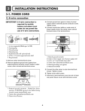
... terminal screw of the terminal block. 1 2 6 34 5 7 1. 4-wire receptacle (NEMA type 14-30R) 2. 4-prong plug 3. Connect neutral wire (white or center wire) of dryer rear panel Secure cover with upturned ends 6. 3/4 in . (1.9 cm) UL-listed strain relief 4. Ground prong 4. External ground connector 2. Tighten screws. 6. POWER CORD 1) 4-wire connection IMPORTANT: A 4-wire connection...
... terminal screw of the terminal block. 1 2 6 34 5 7 1. 4-wire receptacle (NEMA type 14-30R) 2. 4-prong plug 3. Connect neutral wire (white or center wire) of dryer rear panel Secure cover with upturned ends 6. 3/4 in . (1.9 cm) UL-listed strain relief 4. Ground prong 4. External ground connector 2. Tighten screws. 6. POWER CORD 1) 4-wire connection IMPORTANT: A 4-wire connection...
Service Manual
Page 8
... screws. 4. Connect appliance ground wire and the neutral wire (white or center wire) of dryer rear panel. Tighten screw. 3. Tighten strain relief screws. 5. Neutral prong 4. Connect neutral wire (white or center wire) of dryer rear panel. Connect a separate copper ground wire from external ground connector screw. Loosen or remove center terminal block...
... screws. 4. Connect appliance ground wire and the neutral wire (white or center wire) of dryer rear panel. Tighten screw. 3. Tighten strain relief screws. 5. Neutral prong 4. Connect neutral wire (white or center wire) of dryer rear panel. Connect a separate copper ground wire from external ground connector screw. Loosen or remove center terminal block...
Service Manual
Page 27
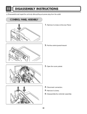
11 DISASSEMBLY INSTRUCTIONS Disassemble and repair the unit only after pulling out power plug from the outlet. 1. Open the cover protect. 4. Remove 3 screws on the rear Panel. 2. Disconnect connectors. 5. Remove 5 screws. 6. Pull the control panel forward. 3. Disassemble the controller assembly. 26
11 DISASSEMBLY INSTRUCTIONS Disassemble and repair the unit only after pulling out power plug from the outlet. 1. Open the cover protect. 4. Remove 3 screws on the rear Panel. 2. Disconnect connectors. 5. Remove 5 screws. 6. Pull the control panel forward. 3. Disassemble the controller assembly. 26

