

Service Manual
Page 17
Contact On / Off by Centrifugal Switch STOP MODE (When Motor does not operate) RUN MODE (Motor operates) Centrifugal switch Centrifugal switch (Pull Drive forward) 17 6 MOTOR DIAGRAM AND SCHEMATIC NOTE When checking Component, be sure to turn Power off, then do voltage discharge sufficiently.
Contact On / Off by Centrifugal Switch STOP MODE (When Motor does not operate) RUN MODE (Motor operates) Centrifugal switch Centrifugal switch (Pull Drive forward) 17 6 MOTOR DIAGRAM AND SCHEMATIC NOTE When checking Component, be sure to turn Power off, then do voltage discharge sufficiently.
Service Manual
Page 23
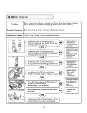
... Caution Before measuring resistance, be sure to turn Power off from • Motor Pulley. • Replace Idler Switch. • Check Motor.(Refer to Motor Bracket operate Level by drum belt? NO Is resistance below 3Ω between Connector "BL2- " (Yellow wire)? ..."BL2- YES NO Is resistance below 3Ω between terminals of Power cord with earth line.) Trouble Symptom Drum will not rotate; Measurement Condition Turn the Dryer's Power Off, then measure resistance. NO YES • Replace Control. (Relay check) • Check Controller connector. • ...
... Caution Before measuring resistance, be sure to turn Power off from • Motor Pulley. • Replace Idler Switch. • Check Motor.(Refer to Motor Bracket operate Level by drum belt? NO Is resistance below 3Ω between Connector "BL2- " (Yellow wire)? ..."BL2- YES NO Is resistance below 3Ω between terminals of Power cord with earth line.) Trouble Symptom Drum will not rotate; Measurement Condition Turn the Dryer's Power Off, then measure resistance. NO YES • Replace Control. (Relay check) • Check Controller connector. • ...

Service Manual
Page 25
...below 1Ω between "WH3- YES • Door switch Check (Refer to Component testing.) • Check Lamp. (When opening Door, Drum motor and Trouble Symptom Heater run continuously; " (Yellow wire) and "WH3- Check if resistance is 300~60Ω between "BL2- YES NO ...; Door switch Check (Refer to Component testing.) Measure while Door is open . Measure while Door is not sensed. (Drum motor will flash at 0.5 second intervals.) Measurement Condition After turning Dryer Power Off, measure resistance. " (White wire) and "RD3- " (Yellow wire) and "WH3- Door Close is...
...below 1Ω between "WH3- YES • Door switch Check (Refer to Component testing.) • Check Lamp. (When opening Door, Drum motor and Trouble Symptom Heater run continuously; " (Yellow wire) and "WH3- Check if resistance is 300~60Ω between "BL2- YES NO ...; Door switch Check (Refer to Component testing.) Measure while Door is open . Measure while Door is not sensed. (Drum motor will flash at 0.5 second intervals.) Measurement Condition After turning Dryer Power Off, measure resistance. " (White wire) and "RD3- " (Yellow wire) and "WH3- Door Close is...
Service Manual
Page 26
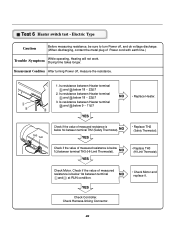
...and below 1Ω between terminal TH2 (Safety Thermostat). Is resistance between Heater terminal and below 1Ω between terminal TH3 (HI-Limit Thermostat). Check Motor. Check if the value of measured resistance is below 18 ~ 22Ω? 3. Is resistance between Heater terminal and below 1Ω between terminal NO... Thermostat). Test 6 Heater switch test - NO YES • Replace TH2 (Safety Thermostat). Electric Type Caution Before measuring resistance, be sure to turn Power off , measure the resistance. YES Check Controller. Drying time takes longer.
...and below 1Ω between terminal TH2 (Safety Thermostat). Is resistance between Heater terminal and below 1Ω between terminal TH3 (HI-Limit Thermostat). Check Motor. Check if the value of measured resistance is below 18 ~ 22Ω? 3. Is resistance between Heater terminal and below 1Ω between terminal NO... Thermostat). Test 6 Heater switch test - NO YES • Replace TH2 (Safety Thermostat). Electric Type Caution Before measuring resistance, be sure to turn Power off , measure the resistance. YES Check Controller. Drying time takes longer.


