
Service Manual
Page 4
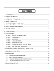
... 29 10. DISASSEMBLY INSTRUCTIONS 32 12. INSTALLATION INSTRUCTIONS 6 4. TEST 5 DOOR SWITCH TEST 27 9-6. ELECTRIC MODEL 28 9-7. DRUM & MOTOR ASSEMBLY: GAS MODEL 42 13. TEST 2 THERMISTOR TEST 24 9-3. TEST 4 MOISTURE SENSOR 26 9-5. EXPLODED VIEW ...39 12-1. DRUM & MOTOR ASSEMBLY: ELECTRIC MODEL 41 12-3-2. TEST 1 120V AC ELECTRICAL SUPPLY 21 9-2. WIRING DIAGRAM ...19 9. TEST...
... 29 10. DISASSEMBLY INSTRUCTIONS 32 12. INSTALLATION INSTRUCTIONS 6 4. TEST 5 DOOR SWITCH TEST 27 9-6. ELECTRIC MODEL 28 9-7. DRUM & MOTOR ASSEMBLY: GAS MODEL 42 13. TEST 2 THERMISTOR TEST 24 9-3. TEST 4 MOISTURE SENSOR 26 9-5. EXPLODED VIEW ...39 12-1. DRUM & MOTOR ASSEMBLY: ELECTRIC MODEL 41 12-3-2. TEST 1 120V AC ELECTRICAL SUPPLY 21 9-2. WIRING DIAGRAM ...19 9. TEST...
Service Manual
Page 6
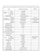
of Dry Levels Sound levels Sensor Moisture Temperature Reversible Door Drum Dryer Rack Child Lock Interior Light Product (WxHxD) Packing (WxHxD) DLE2516W / DLG2526W Blue White Porcelain Silver Spray 120V/240V 60Hz (26A) 250W (4.5A) 5400W (22.... sensor Thermistor of Dry Options No. ITEM Material & Finish Color Top Plate Door Trim POWER SUPPLY ELECTRICITY CONSUMPTION MOTOR HEATER LAMP GAS VALVE CONTROL TYPE DRUM CAPACITY Weight (lbs) - of Programs No. of Temperature Controls No. Net/Gross No.
of Dry Levels Sound levels Sensor Moisture Temperature Reversible Door Drum Dryer Rack Child Lock Interior Light Product (WxHxD) Packing (WxHxD) DLE2516W / DLG2526W Blue White Porcelain Silver Spray 120V/240V 60Hz (26A) 250W (4.5A) 5400W (22.... sensor Thermistor of Dry Options No. ITEM Material & Finish Color Top Plate Door Trim POWER SUPPLY ELECTRICITY CONSUMPTION MOTOR HEATER LAMP GAS VALVE CONTROL TYPE DRUM CAPACITY Weight (lbs) - of Programs No. of Temperature Controls No. Net/Gross No.
Service Manual
Page 7
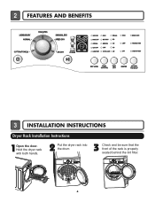
Hold the dryer rack with both hands. 2 Put the dryer rack into the drum 3 Check and be sure that the front of the rack is properly seated behind the lint filter. 6 2 FEATURES AND BENEFITS 3 INSTALLATION INSTRUCTIONS Dryer Rack Installation Instructions 1Open the door.
Hold the dryer rack with both hands. 2 Put the dryer rack into the drum 3 Check and be sure that the front of the rack is properly seated behind the lint filter. 6 2 FEATURES AND BENEFITS 3 INSTALLATION INSTRUCTIONS Dryer Rack Installation Instructions 1Open the door.
Service Manual
Page 21
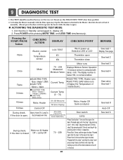
... Operation: If moisture sensor is open the door. Current Temp. (5 ~ 70) ELECTRIC TYPE: Heater runs GAS TYPE: GAS Valve runs (Display the Temperature of Inside drum.) 4 times Motor, Heater 50~230 Measured "SE"(Error Display) Motor, Heater Off Semi-conductor 5 times Control Off During check, If the door is contacted with...
... Operation: If moisture sensor is open the door. Current Temp. (5 ~ 70) ELECTRIC TYPE: Heater runs GAS TYPE: GAS Valve runs (Display the Temperature of Inside drum.) 4 times Motor, Heater 50~230 Measured "SE"(Error Display) Motor, Heater Off Semi-conductor 5 times Control Off During check, If the door is contacted with...
Service Manual
Page 26
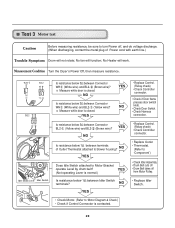
...8226; Check Controller connector. • Replace Outlet • Thermostat. (Refer to 'Component') • Check Idler Assembly. • Drum Belt cuts off • Drum Belt takes off , and do voltage discharge. (When discharging, contact the metal plug of Outlet Thermostat attached to blower housing? Measurement Condition... between Idler Switch terminals? Measure while door is closed . NO YES Does Idle Switch attached to Motor Bracket operate Level by drum belt? No Heater will function; No fan will work. Test 3 Motor test Caution Before measuring resistance, be sure to turn...
...8226; Check Controller connector. • Replace Outlet • Thermostat. (Refer to 'Component') • Check Idler Assembly. • Drum Belt cuts off • Drum Belt takes off , and do voltage discharge. (When discharging, contact the metal plug of Outlet Thermostat attached to blower housing? Measurement Condition... between Idler Switch terminals? Measure while door is closed . NO YES Does Idle Switch attached to Motor Bracket operate Level by drum belt? No Heater will function; No fan will work. Test 3 Motor test Caution Before measuring resistance, be sure to turn...
Service Manual
Page 28
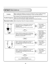
...• Door switch Check (Refer to Component testing.) Check Controller. Check Harness-linking connector. 27 Check it resistance is not sensed. (Drum motor will flash at 0.5 second intervals.) Measurement Condition After turning Dryer Power Off, measure resistance. Check it resistance is open . YES ...BL2 NO out from Controller. YES • Door switch Check (Refer to Component testing.) • Check Lamp. (When opening Door, Drum motor and Trouble Symptom Heater run continuously) Door Close is below 1 Ω between WH1- (White wire) and BK2(Black wire). Display will ...
...• Door switch Check (Refer to Component testing.) Check Controller. Check Harness-linking connector. 27 Check it resistance is not sensed. (Drum motor will flash at 0.5 second intervals.) Measurement Condition After turning Dryer Power Off, measure resistance. Check it resistance is open . YES ...BL2 NO out from Controller. YES • Door switch Check (Refer to Component testing.) • Check Lamp. (When opening Door, Drum motor and Trouble Symptom Heater run continuously) Door Close is below 1 Ω between WH1- (White wire) and BK2(Black wire). Display will ...

Service Manual
Page 36
...]. 3. Hold the lamp shield in place while removing the screw. 3. Remove Cover Cabinet. 3. Disassemble the Tub Drum [Front]. 1. Remove the bulb and replace with a 15 watt, 120 volt candelabra-base bulb. 5. When you disassemble the lamp connector, be sure to ...do so can cause serious injury. 1. Disconnect the door lamp and electrode sensor connector. 4. Remove 4 screws. 5. CHANGING THE DRUM LAMP 1. Loosen belt from motor and idler pulleys. 4. Failure to take gloves and careful cabinet edge. Slide the shield up and remove. 4. Replace the lamp...
...]. 3. Hold the lamp shield in place while removing the screw. 3. Remove Cover Cabinet. 3. Disassemble the Tub Drum [Front]. 1. Remove the bulb and replace with a 15 watt, 120 volt candelabra-base bulb. 5. When you disassemble the lamp connector, be sure to ...do so can cause serious injury. 1. Disconnect the door lamp and electrode sensor connector. 4. Remove 4 screws. 5. CHANGING THE DRUM LAMP 1. Loosen belt from motor and idler pulleys. 4. Failure to take gloves and careful cabinet edge. Slide the shield up and remove. 4. Replace the lamp...
Service Manual
Page 38
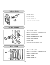
1. Disassemble the top plate. 2. Disassemble the top plate. 2. Remove the Cover Grid. 4. Disconnect the electrode sensor. 1. Remove 2 screws and cover (Air guide). 5. Remove the Cabinet Cover and Tub Drum [Front]. 3. Disconnect the motor clamp and motor. 1. Remove the Back Cover. 37 Remove the bolt and washer. 6. Remove the Drum assembly. 4. Remove the filter. 2. Remove 7 screws. 5. Remove the Cabinet Cover and Tub Drum [Front]. 3. Remove the Drum assembly. 4. Remove the fan. 7. Remove 3 screws. 3.
1. Disassemble the top plate. 2. Disassemble the top plate. 2. Remove the Cover Grid. 4. Disconnect the electrode sensor. 1. Remove 2 screws and cover (Air guide). 5. Remove the Cabinet Cover and Tub Drum [Front]. 3. Disconnect the motor clamp and motor. 1. Remove the Back Cover. 37 Remove the bolt and washer. 6. Remove the Drum assembly. 4. Remove the filter. 2. Remove 7 screws. 5. Remove the Cabinet Cover and Tub Drum [Front]. 3. Remove the Drum assembly. 4. Remove the fan. 7. Remove 3 screws. 3.

Service Manual
Page 39
1. Disconnect the Air duct from the Tub Drum [Front] and Tub Drum [Rear]. 38 Disassemble the top plate. 2. Remove the Drum assembly and Tub Drum [Rear]. 4. Remove the roller from the Tub Drum [Front]. 5. Disassemble the top plate. 2. Remove the air duct. 1. Remove the Cover Cabinet and Tub Drum [Front]. 3. Remove the filter and 2 screws. 4. Remove the Cover Cabinet. 3.
1. Disconnect the Air duct from the Tub Drum [Front] and Tub Drum [Rear]. 38 Disassemble the top plate. 2. Remove the Drum assembly and Tub Drum [Rear]. 4. Remove the roller from the Tub Drum [Front]. 5. Disassemble the top plate. 2. Remove the air duct. 1. Remove the Cover Cabinet and Tub Drum [Front]. 3. Remove the filter and 2 screws. 4. Remove the Cover Cabinet. 3.

Service Manual
Page 42
12-3-1. Drum & Motor Assembly: Electric Type F200 K400 K120 K140 K100 K130 K222 K221 K210 K350 K240 F130 F110 F120 K250 K251 K310 K330 K320 K340 K620 K230 K250 K360 K610 K550 K560 K251 F140 K540 K510 K520 K530 K640 K651 K650 K600 41
12-3-1. Drum & Motor Assembly: Electric Type F200 K400 K120 K140 K100 K130 K222 K221 K210 K350 K240 F130 F110 F120 K250 K251 K310 K330 K320 K340 K620 K230 K250 K360 K610 K550 K560 K251 F140 K540 K510 K520 K530 K640 K651 K650 K600 41
Service Manual
Page 44
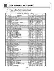
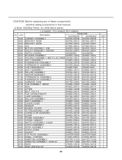
...in this manual. ¡Æ Note: S(Safety Parts), AL (Alternative parts) LG MODEL: TD-V10062E, TD-V10060E AL LOC Description Model P/No DLE2512W DLE2514W A500 CABINET ASSEMBLY 3091EL0003A 3091EL0003A K610 MOTOR ASSEMBLY. WM 4681EL1002A 4681EL1002A A520 BRACKET,... K530 DUCT ASSEMBLY 5209EL1006A 5209EL1006A K550 THERMISTOR ASSEMBLY 6323EL2001B 6323EL2001B K560 THERMOSTAT ASSEMBLY 6931EL3002A 6931EL3002A K400 TUB, DRUM [BACK] F200 DUCT ASSEMBLY 3044EL002C 3044EL002C 5209EL1001C 5209EL1001C K250 ROLLER ASSEMBLY F110 HEATER ASSEMBLY 4581EL3001A 4581EL3001A 5301EL1001E...
...in this manual. ¡Æ Note: S(Safety Parts), AL (Alternative parts) LG MODEL: TD-V10062E, TD-V10060E AL LOC Description Model P/No DLE2512W DLE2514W A500 CABINET ASSEMBLY 3091EL0003A 3091EL0003A K610 MOTOR ASSEMBLY. WM 4681EL1002A 4681EL1002A A520 BRACKET,... K530 DUCT ASSEMBLY 5209EL1006A 5209EL1006A K550 THERMISTOR ASSEMBLY 6323EL2001B 6323EL2001B K560 THERMOSTAT ASSEMBLY 6931EL3002A 6931EL3002A K400 TUB, DRUM [BACK] F200 DUCT ASSEMBLY 3044EL002C 3044EL002C 5209EL1001C 5209EL1001C K250 ROLLER ASSEMBLY F110 HEATER ASSEMBLY 4581EL3001A 4581EL3001A 5301EL1001E...
Service Manual
Page 45
..., read the safety precautions in this manual. ¡Æ Note: S(Safety Parts), AL (Alternative parts) LG MODEL: TD-V10062G,TD-V10060G AL LOC Description Model P/N DLE2522W DLE2524W A500 CABINET ASSEMBLY 3091EL0003B 3091EL0003B A520 BRACKET,... 3661EL1001C K530 DUCT ASSEMBLY 5209EL1006A 5209EL1006A K550 THERMISTOR ASSEMBLY 6323EL2001B 6323EL2001B K560 THERMOSTAT ASSEMBLY 6931EL3002A 6931EL3002A K400 TUB, DRUM [BACK] 3044EL002C 3044EL002C F200 DUCT ASSEMBLY 5209EL1001C 5209EL1001C K250 ROLLER ASSEMBLY 4581EL3001A 4581EL3001A F110 HEATER ASSEMBLY 5301EL1001E 5301EL1001E...
..., read the safety precautions in this manual. ¡Æ Note: S(Safety Parts), AL (Alternative parts) LG MODEL: TD-V10062G,TD-V10060G AL LOC Description Model P/N DLE2522W DLE2524W A500 CABINET ASSEMBLY 3091EL0003B 3091EL0003B A520 BRACKET,... 3661EL1001C K530 DUCT ASSEMBLY 5209EL1006A 5209EL1006A K550 THERMISTOR ASSEMBLY 6323EL2001B 6323EL2001B K560 THERMOSTAT ASSEMBLY 6931EL3002A 6931EL3002A K400 TUB, DRUM [BACK] 3044EL002C 3044EL002C F200 DUCT ASSEMBLY 5209EL1001C 5209EL1001C K250 ROLLER ASSEMBLY 4581EL3001A 4581EL3001A F110 HEATER ASSEMBLY 5301EL1001E 5301EL1001E...


