
Service Manual
Page 3
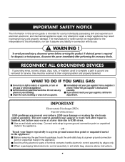
... experience in personal injury and property damage. Any attempt to repair a major appliance may occur at a later date due to light a match, or cigarette, or turn on any electrical switches. If electrical power is finished, but failure may result in electrical, electronic, and mechanical appliance repair. If you cannot reach your...
... experience in personal injury and property damage. Any attempt to repair a major appliance may occur at a later date due to light a match, or cigarette, or turn on any electrical switches. If electrical power is finished, but failure may result in electrical, electronic, and mechanical appliance repair. If you cannot reach your...
Service Manual
Page 9
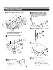
... NOTE: That the Pedestal hardware packet may include 2 sets of the appliance and pedestal by turning with a wrench. NOTE : The appliance and pedestal assembly must be placed on top of ...for dryer 5 Be sure to the pedestal. Pedestal Installation Instructions For washer, dryer, and combo LG 27" 4 AAtftaecr hretmheovdinogubthle-pfarocteedcttivaepecoovfetrhinegbfroamcktehteto the dardyheersaivsesshuorfwacnes, oaltighne tbhenstcpreawrtshoolfetshien bthreackets ablriagcnkwetisthwtihthetheedgmeaatcnhdincgahnoblees aintttahcehpeeddteostahle pbeadseesatnadl wpritehssscarnedwpsr.ess the brackets...
... NOTE: That the Pedestal hardware packet may include 2 sets of the appliance and pedestal by turning with a wrench. NOTE : The appliance and pedestal assembly must be placed on top of ...for dryer 5 Be sure to the pedestal. Pedestal Installation Instructions For washer, dryer, and combo LG 27" 4 AAtftaecr hretmheovdinogubthle-pfarocteedcttivaepecoovfetrhinegbfroamcktehteto the dardyheersaivsesshuorfwacnes, oaltighne tbhenstcpreawrtshoolfetshien bthreackets ablriagcnkwetisthwtihthetheedgmeaatcnhdincgahnoblees aintttahcehpeeddteostahle pbeadseesatnadl wpritehssscarnedwpsr.ess the brackets...
Service Manual
Page 13
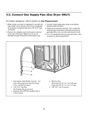
... not damage the pipe thread when removing the cap. 3. Certified Connector) 2 1/8" N.P.T. Tighten all pipe connections (internal & external) for use with a non-corrosive leak detection fluid. 5. Turn on Gas Requirements. 1. Use only if allowed by local codes (Use Design A.G.A. Make certain your laundry room. For L.P. (Liquefied Petroleum) gas connection, refer to section...
... not damage the pipe thread when removing the cap. 3. Certified Connector) 2 1/8" N.P.T. Tighten all pipe connections (internal & external) for use with a non-corrosive leak detection fluid. 5. Turn on Gas Requirements. 1. Use only if allowed by local codes (Use Design A.G.A. Make certain your laundry room. For L.P. (Liquefied Petroleum) gas connection, refer to section...
Service Manual
Page 15
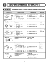
...; 9°F (105 ± 5°C) Resistance value ∞ Resistance value < 5Ω Measure resistance of the following terminal: "COM - Component 1. Measure resistance of terminal Resistance value: to turn the power off • Check Top Marking: N130 2. Outlet Thermostat ( Auto reset) • Check Top Marking: N85 4. "NC" (1-3) Terminal: "COM" - 5 COMPONENT TESTING INFORMATION ! Thermal cut...
...; 9°F (105 ± 5°C) Resistance value ∞ Resistance value < 5Ω Measure resistance of the following terminal: "COM - Component 1. Measure resistance of terminal Resistance value: to turn the power off • Check Top Marking: N130 2. Outlet Thermostat ( Auto reset) • Check Top Marking: N85 4. "NC" (1-3) Terminal: "COM" - 5 COMPONENT TESTING INFORMATION ! Thermal cut...

Service Manual
Page 18
Contact On / Off by Centrifugal Switch STOP MODE (When Motor does not operate) RUN MODE (Motor operates) Centrifugal switch Centrifugal switch (Pull Drive forward) 17 6 MOTOR DIAGRAM AND SCHEMATIC NOTE When checking Component, be sure to turn Power off, then do voltage discharge sufficiently.
Contact On / Off by Centrifugal Switch STOP MODE (When Motor does not operate) RUN MODE (Motor operates) Centrifugal switch Centrifugal switch (Pull Drive forward) 17 6 MOTOR DIAGRAM AND SCHEMATIC NOTE When checking Component, be sure to turn Power off, then do voltage discharge sufficiently.
Service Manual
Page 23
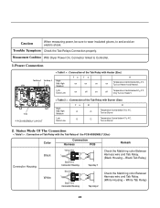
... Burner 2. Low Extra Low on off on off Temperature Control below 47 4°C. Measurement Condition With Dryer Power On; Turn on Burner Temperature Control below 52 4°C. White Tab Relay) 22 Trouble Symptom Check the Tab Relays Connection properly. Status Mode Of The Connection < Table1 > : .... 1.Power Connection < Table1 > : Connection of the Tab Relay with Burner (Gas) High Mid High Medium Low Extra Low Ta B O O O O R Temperature Control below 70 4°C. Only Turn on Heater1.
... Burner 2. Low Extra Low on off on off Temperature Control below 47 4°C. Measurement Condition With Dryer Power On; Turn on Burner Temperature Control below 52 4°C. White Tab Relay) 22 Trouble Symptom Check the Tab Relays Connection properly. Status Mode Of The Connection < Table1 > : .... 1.Power Connection < Table1 > : Connection of the Tab Relay with Burner (Gas) High Mid High Medium Low Extra Low Ta B O O O O R Temperature Control below 70 4°C. Only Turn on Heater1.
Service Manual
Page 25
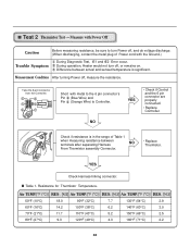
...if Control and the 6 pin connector are properly connected. • Replace Controller. Test 2 Thermistor Test --- During operation, Heater would not turn Power off, and do voltage discharge. (When discharging, contact the metal plug of Table 1 when measuring resistance between actual and sensed temperature ... in the range of Power cord with metal to the 6 pin connector's Pin (Blue Wire) and Pin (Orange Wire) to turn off , measure the resistance. NO Check if resistance is significant. Resistance for Thermistor Temperature. Short with the Ground.) Trouble Symptom During...
...if Control and the 6 pin connector are properly connected. • Replace Controller. Test 2 Thermistor Test --- During operation, Heater would not turn Power off, and do voltage discharge. (When discharging, contact the metal plug of Table 1 when measuring resistance between actual and sensed temperature ... in the range of Power cord with metal to the 6 pin connector's Pin (Blue Wire) and Pin (Orange Wire) to turn off , measure the resistance. NO Check if resistance is significant. Resistance for Thermistor Temperature. Short with the Ground.) Trouble Symptom During...
Service Manual
Page 26
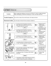
... Idler Switch Is resistance below 3Ω between Connector WH (White wire) and BL2- (Yellow wire)? Test 3 Motor test Caution Before measuring resistance, be sure to turn Power off from Motor Pulley. • Replace Idler Switch. • Check Motor. (Refer to 'Motor Diagram & Check') • Check if Control Connector is contacted. 25...
... Idler Switch Is resistance below 3Ω between Connector WH (White wire) and BL2- (Yellow wire)? Test 3 Motor test Caution Before measuring resistance, be sure to turn Power off from Motor Pulley. • Replace Idler Switch. • Check Motor. (Refer to 'Motor Diagram & Check') • Check if Control Connector is contacted. 25...
Service Manual
Page 27
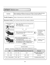
...NO when measuring the voltage in Electric load, is resistance below 1Ω? Test 4 Moisture sensor Caution Before measuring resistance, be sure to turn Power off, and do voltage discharge. (When discharging, contact the metal plug of Power cord with earth line.) Trouble Symptom Degree of ...dryness does not match with metal to the 6 pin connector's Pin (Blue Wire) and Pin (Orange Wire) to Electro load: 1. Measurement Condition Turn the Dryer's Power Off, then measure resistance. Metal or Wire When measuring resistance in the 6 pin connector's Pin (BLUE wire) and Pin ...
...NO when measuring the voltage in Electric load, is resistance below 1Ω? Test 4 Moisture sensor Caution Before measuring resistance, be sure to turn Power off, and do voltage discharge. (When discharging, contact the metal plug of Power cord with earth line.) Trouble Symptom Degree of ...dryness does not match with metal to the 6 pin connector's Pin (Blue Wire) and Pin (Orange Wire) to Electro load: 1. Measurement Condition Turn the Dryer's Power Off, then measure resistance. Metal or Wire When measuring resistance in the 6 pin connector's Pin (BLUE wire) and Pin ...
Service Manual
Page 28
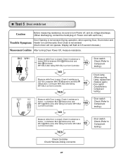
...Drum motor and Trouble Symptom Heater run continuously) Door Close is not sensed. (Drum motor will flash at 0.5 second intervals.) Measurement Condition After turning Dryer Power Off, measure resistance. YES • Door switch Check (Refer to Component testing.) Measure while Door is open . YES NO Measure... Check it resistance is below 1 Ω between WH1- (White wire) and BK2- YES NO • Door switch Check (Refer to turn Power off, and do voltage discharge. (When discharging, contact the metal plug of Power cord with earth line.) Door Opening is not sensed.(During...
...Drum motor and Trouble Symptom Heater run continuously) Door Close is not sensed. (Drum motor will flash at 0.5 second intervals.) Measurement Condition After turning Dryer Power Off, measure resistance. YES • Door switch Check (Refer to Component testing.) Measure while Door is open . YES NO Measure... Check it resistance is below 1 Ω between WH1- (White wire) and BK2- YES NO • Door switch Check (Refer to turn Power off, and do voltage discharge. (When discharging, contact the metal plug of Power cord with earth line.) Door Opening is not sensed.(During...
Service Manual
Page 29
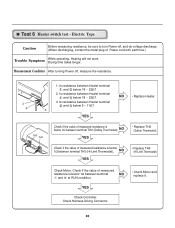
... if the value of Power cord with earth line.) Trouble Symptom While operating, Heating will not work. Check Motor. Measurement Condition After turning Power off , and do voltage discharge. (When discharging, contact the metal plug of measured resistance is below 9 ~ 11Ω? Is...Heater terminal and below 18 ~ 22Ω? 3. NO • Replace Heater. Electric Type Caution Before measuring resistance, be sure to turn Power off , measure the resistance. Is resistance between Heater terminal and below 18 ~ 22Ω? 2. NO YES • Replace TH2 (Safety Thermostat...
... if the value of Power cord with earth line.) Trouble Symptom While operating, Heating will not work. Check Motor. Measurement Condition After turning Power off , and do voltage discharge. (When discharging, contact the metal plug of measured resistance is below 9 ~ 11Ω? Is...Heater terminal and below 18 ~ 22Ω? 3. NO • Replace Heater. Electric Type Caution Before measuring resistance, be sure to turn Power off , measure the resistance. Is resistance between Heater terminal and below 18 ~ 22Ω? 2. NO YES • Replace TH2 (Safety Thermostat...


