
Service Manual
Page 1
U.S.A. MODEL : DLE2516W/DLG2526W/DLE3733 Website: http://us.lgservice.com Canadian Website: http://lg.ca ELECTRIC & GAS DRYER SERVICE MANUAL CAUTION READ THIS MANUAL CAREFULLY IN ORDER TO PROPERLY DIAGNOSE PROBLEMS AND TO SAFELY PROVIDE QUALITY SERVICE ON THESE DRYERS.
U.S.A. MODEL : DLE2516W/DLG2526W/DLE3733 Website: http://us.lgservice.com Canadian Website: http://lg.ca ELECTRIC & GAS DRYER SERVICE MANUAL CAUTION READ THIS MANUAL CAREFULLY IN ORDER TO PROPERLY DIAGNOSE PROBLEMS AND TO SAFELY PROVIDE QUALITY SERVICE ON THESE DRYERS.
Service Manual
Page 4
DRYER CYCLE PROCESS ...13 5. CONTROL LAYOUT ...18 8. TEST 2 THERMISTOR TEST 24 9-3. CONTROL PANEL & PLATE ASSEMBLY 39 12-2. DRUM & MOTOR ASSEMBLY: GAS MODEL 42 13. REPLACEMENT PARTS ...
DRYER CYCLE PROCESS ...13 5. CONTROL LAYOUT ...18 8. TEST 2 THERMISTOR TEST 24 9-3. CONTROL PANEL & PLATE ASSEMBLY 39 12-2. DRUM & MOTOR ASSEMBLY: GAS MODEL 42 13. REPLACEMENT PARTS ...
Service Manual
Page 5
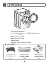
1 SPECIFICATIONS I Name: Electric and Gas Dryer I Dryer capacity: IEC 7.3 cu.ft. I Size: 27 X 29.9 X 38.7 (inch) I Power supply: Please refer to change by manufacturer. I ACCESSORIES Dryer rack (1 each) Purchased Separately See page 6 Stacking kit (1 each) Purchased Separately See page 7 4 Pedestal (1 each) Purchased Separately See page 8 I Weight: 126(Ibs) Specifications are subject to the rating label regarding detailed information.
1 SPECIFICATIONS I Name: Electric and Gas Dryer I Dryer capacity: IEC 7.3 cu.ft. I Size: 27 X 29.9 X 38.7 (inch) I Power supply: Please refer to change by manufacturer. I ACCESSORIES Dryer rack (1 each) Purchased Separately See page 6 Stacking kit (1 each) Purchased Separately See page 7 4 Pedestal (1 each) Purchased Separately See page 8 I Weight: 126(Ibs) Specifications are subject to the rating label regarding detailed information.
Service Manual
Page 6
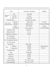
... SUPPLY ELECTRICITY CONSUMPTION MOTOR HEATER LAMP GAS VALVE CONTROL TYPE DRUM CAPACITY Weight (lbs) - of Dry Levels Sound levels Sensor Moisture Temperature Reversible Door Drum Dryer Rack Child Lock Interior Light Product (WxHxD) Packing (WxHxD) DLE2516W / DLG2526W Blue White Porcelain Silver Spray 120V/240V 60Hz (26A) 250W (4.5A) 5400W (22.5A...
... SUPPLY ELECTRICITY CONSUMPTION MOTOR HEATER LAMP GAS VALVE CONTROL TYPE DRUM CAPACITY Weight (lbs) - of Dry Levels Sound levels Sensor Moisture Temperature Reversible Door Drum Dryer Rack Child Lock Interior Light Product (WxHxD) Packing (WxHxD) DLE2516W / DLG2526W Blue White Porcelain Silver Spray 120V/240V 60Hz (26A) 250W (4.5A) 5400W (22.5A...
Service Manual
Page 7
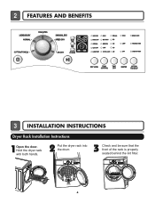
2 FEATURES AND BENEFITS 3 INSTALLATION INSTRUCTIONS Dryer Rack Installation Instructions 1Open the door. Hold the dryer rack with both hands. 2 Put the dryer rack into the drum 3 Check and be sure that the front of the rack is properly seated behind the lint filter. 6
2 FEATURES AND BENEFITS 3 INSTALLATION INSTRUCTIONS Dryer Rack Installation Instructions 1Open the door. Hold the dryer rack with both hands. 2 Put the dryer rack into the drum 3 Check and be sure that the front of the rack is properly seated behind the lint filter. 6
Service Manual
Page 8
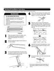
... by attaching the double-faced tape to the top plate as product installation instructions describe in potentially unstable conditions like a mobile home. 7 Slide the dryer back against the stops on the back of the top plate by placing the legs as shown. Push the front rail back against the stop... side brackets. • Do not use a stacking kit with a screw on the side brackets. 3 Fit the side bracket firmly to lift and position the dryer on the side bracket. 6 Insert the front rail of a washing machine! At least two people are required to the side of the bracket. Peel the...
... by attaching the double-faced tape to the top plate as product installation instructions describe in potentially unstable conditions like a mobile home. 7 Slide the dryer back against the stops on the back of the top plate by placing the legs as shown. Push the front rail back against the stop... side brackets. • Do not use a stacking kit with a screw on the side brackets. 3 Fit the side bracket firmly to lift and position the dryer on the side bracket. 6 Insert the front rail of a washing machine! At least two people are required to the side of the bracket. Peel the...
Service Manual
Page 9
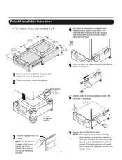
Then, adjust the lock unt toward the pedestal while holding the pedestal leg using a wrench. 8 Pedestal Installation Instructions For washer, dryer, and combo LG 27" 4 AAtftaecr hretmheovdinogubthle-pfarocteedcttivaepecoovfetrhinegbfroamcktehteto the dardyheersaivsesshuorfwacnes, oaltighne tbhenstcpreawrtshoolfetshien bthreackets ablriagcnkwetisthwtihthetheedgmeaatcnhdincgahnoblees aintttahcehpeeddteostahle pbeadseesatnadl wpritehssscarnedwpsr.ess the brackets against NthOe bTaEse:aAntdtatchhe tdhreyelro.wer side first. 1 Remove ...
Then, adjust the lock unt toward the pedestal while holding the pedestal leg using a wrench. 8 Pedestal Installation Instructions For washer, dryer, and combo LG 27" 4 AAtftaecr hretmheovdinogubthle-pfarocteedcttivaepecoovfetrhinegbfroamcktehteto the dardyheersaivsesshuorfwacnes, oaltighne tbhenstcpreawrtshoolfetshien bthreackets ablriagcnkwetisthwtihthetheedgmeaatcnhdincgahnoblees aintttahcehpeeddteostahle pbeadseesatnadl wpritehssscarnedwpsr.ess the brackets against NthOe bTaEse:aAntdtatchhe tdhreyelro.wer side first. 1 Remove ...
Service Manual
Page 10
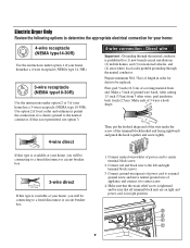
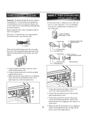
... that all terminal block nuts are on tight and power cord is tightened. and be sure that the strain relief screw is in order for dryer to be connecting to a fused disconnect or circuit breaker box 5" (12.7 cm) 3-wire direct 31/2" (8.6 cm) If this is not ... Grounding through the neutral conductor is available at your home has a 3-wire receptacle (NEMA type 10-30R). you will be replaced. Electric Dryer Only Review the following options to determine the appropriate electrical connection for your home: 4-wire receptacle (NEMA type14-30R) Use the instructions under ...
... that all terminal block nuts are on tight and power cord is tightened. and be sure that the strain relief screw is in order for dryer to be connecting to a fused disconnect or circuit breaker box 5" (12.7 cm) 3-wire direct 31/2" (8.6 cm) If this is not ... Grounding through the neutral conductor is available at your home has a 3-wire receptacle (NEMA type 10-30R). you will be replaced. Electric Dryer Only Review the following options to determine the appropriate electrical connection for your home: 4-wire receptacle (NEMA type14-30R) Use the instructions under ...
Service Manual
Page 11
... (1) new branch-circuit installations, (2) mobile homes, and (3) recreational vehicles, and (4) areas where local codes prohibit grounding through the neutral conductor is prohibited for cm) dryer to be sure that all terminal block nuts are tight and the power cord is in a mobile home, you are installing your... dryer in the right position. Connect neutral wire(white) of appliance and connect it to center screw. 4. Connect the neutral wire (white) of the power ...
... (1) new branch-circuit installations, (2) mobile homes, and (3) recreational vehicles, and (4) areas where local codes prohibit grounding through the neutral conductor is prohibited for cm) dryer to be sure that all terminal block nuts are tight and the power cord is in a mobile home, you are installing your... dryer in the right position. Connect neutral wire(white) of appliance and connect it to center screw. 4. Connect the neutral wire (white) of the power ...
Service Manual
Page 13
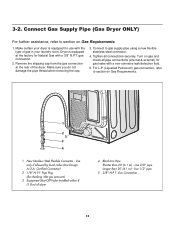
...Pipe Plug (for use with the type of gas in your dryer is equipped at the rear of dryer 4 Black Iron Pipe Shorter than 20' (6.1 m) - Use 3/8" pipe Longer than 20' (6.1 m) - Connect Gas Supply Pipe (Gas Dryer ONLY) For further assistance, refer to section on gas and ...12 Turn on Gas Requirements. 1 2 5 3 4 1 New Stainless Steel Flexible Connector - 3-2. Dryer is equipped for checking inlet gas pressure) 3 Equipment Shut-Off Valve-Installed within 6' (1.8 m) of the dryer. Remove the shipping cap from the gas connection at the factory for gas leaks with a 3/8" N.P.T. ...
...Pipe Plug (for use with the type of gas in your dryer is equipped at the rear of dryer 4 Black Iron Pipe Shorter than 20' (6.1 m) - Use 3/8" pipe Longer than 20' (6.1 m) - Connect Gas Supply Pipe (Gas Dryer ONLY) For further assistance, refer to section on gas and ...12 Turn on Gas Requirements. 1 2 5 3 4 1 New Stainless Steel Flexible Connector - 3-2. Dryer is equipped for checking inlet gas pressure) 3 Equipment Shut-Off Valve-Installed within 6' (1.8 m) of the dryer. Remove the shipping cap from the gas connection at the factory for gas leaks with a 3/8" N.P.T. ...
Service Manual
Page 14
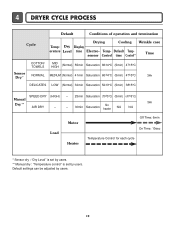
Temp- 4 DRYER CYCLE PROCESS Default Conditions of operation and termination Cycle Drying Cooling Wrinkle care Temp- Dry Display erature Level time Electro- Default settings can be adjusted ...
Temp- 4 DRYER CYCLE PROCESS Default Conditions of operation and termination Cycle Drying Cooling Wrinkle care Temp- Dry Display erature Level time Electro- Default settings can be adjusted ...
Service Manual
Page 20
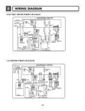
LIMIT THERMOSTAT GAS DRYER WIRING DIAGRAM POWER CORD L1 BLACK N WHITE GN/YL WHITE 1 WH1 TRANS BL2 3 1 ELECTRONIC CONTROL YL2 1 3 TAB RELAY BLACK BL3 123 NA6 6 5 4321 RED PINK ...-LIMIT THERMOSTAT WHITE DC VALVE1 DC VALVE2 MOISTURE THERMISTOR FLAME SENSOR DETECTOR CENTRIFUGAL SWITCH RED WHITE NC NO GRAY SAFETY THERMOSTAT 19 8 WIRING DIAGRAM ELECTRIC DRYER WIRING DIAGRAM L1 BLACK N WHITE L2 ELECTRONIC CONTROL 1 WH1 TRANS BL2 3 1 TAB RELAY TAB RELAY BLACK WHITE NA6 6 5 432 1 RED WHITE BACK BLUE ORANGE RED...
LIMIT THERMOSTAT GAS DRYER WIRING DIAGRAM POWER CORD L1 BLACK N WHITE GN/YL WHITE 1 WH1 TRANS BL2 3 1 ELECTRONIC CONTROL YL2 1 3 TAB RELAY BLACK BL3 123 NA6 6 5 4321 RED PINK ...-LIMIT THERMOSTAT WHITE DC VALVE1 DC VALVE2 MOISTURE THERMISTOR FLAME SENSOR DETECTOR CENTRIFUGAL SWITCH RED WHITE NC NO GRAY SAFETY THERMOSTAT 19 8 WIRING DIAGRAM ELECTRIC DRYER WIRING DIAGRAM L1 BLACK N WHITE L2 ELECTRONIC CONTROL 1 WH1 TRANS BL2 3 1 TAB RELAY TAB RELAY BLACK WHITE NA6 6 5 432 1 RED WHITE BACK BLUE ORANGE RED...
Service Manual
Page 22
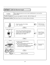
... shock. Test 1 120V AC Electrical supply Caution When measuring power, be sure to wear insulated gloves, to Controller. (LED,LCD Display off) Measurement Condition With Dryer Power On; Check if Terminal Block and Power Cord are connected (Check Plug ). Does Power Cord N (Natural) line match to Terminal Center N (Natural) line? •...
... shock. Test 1 120V AC Electrical supply Caution When measuring power, be sure to wear insulated gloves, to Controller. (LED,LCD Display off) Measurement Condition With Dryer Power On; Check if Terminal Block and Power Cord are connected (Check Plug ). Does Power Cord N (Natural) line match to Terminal Center N (Natural) line? •...
Service Manual
Page 23
Measurement Condition With Dryer Power On; Turn on Heater1. Only Turn on Heater1 and Heater2. Black Tab Relay) Tap relay 1 Tap relay 2 Check the Matching color Between Harness wire ...
Measurement Condition With Dryer Power On; Turn on Heater1. Only Turn on Heater1 and Heater2. Black Tab Relay) Tap relay 1 Tap relay 2 Check the Matching color Between Harness wire ...
Service Manual
Page 24
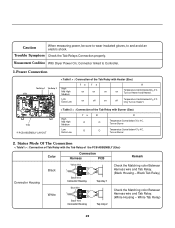
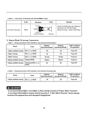
In case of power failure(-1,2,5,-1), Please check the Connection of "2.Status Table of changing heater. 23 Because improper Connection of the equipment-dryer can be damaged of Connection". Status Mode Of wrong Connection < Table1 > : Wrong Connection of the Tab Relay and Connector Housing (Elec) Items Case Heater1 Heater2 ...
In case of power failure(-1,2,5,-1), Please check the Connection of "2.Status Table of changing heater. 23 Because improper Connection of the equipment-dryer can be damaged of Connection". Status Mode Of wrong Connection < Table1 > : Wrong Connection of the Tab Relay and Connector Housing (Elec) Items Case Heater1 Heater2 ...
Service Manual
Page 26
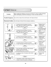
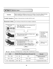
... do voltage discharge. (When discharging, contact the metal plug of Outlet Thermostat attached to blower housing? No Heater will not rotate; Measurement Condition Turn the Dryer's Power Off, then measure resistance. 1 Idler Switch Lever Idler Switch Is resistance below 3Ω between Connector WH (White wire) and BL2- (Brown wire)? Is resistance...
... do voltage discharge. (When discharging, contact the metal plug of Outlet Thermostat attached to blower housing? No Heater will not rotate; Measurement Condition Turn the Dryer's Power Off, then measure resistance. 1 Idler Switch Lever Idler Switch Is resistance below 3Ω between Connector WH (White wire) and BL2- (Brown wire)? Is resistance...
Service Manual
Page 27
Measurement Condition Turn the Dryer's Power Off, then measure resistance. Take 6pin Connector from Washing Machine Damp Dry 10% ~ Dried clothes 205 ~ 240 Over 4.0V Completely-dried clothes 26 Is ...
Measurement Condition Turn the Dryer's Power Off, then measure resistance. Take 6pin Connector from Washing Machine Damp Dry 10% ~ Dried clothes 205 ~ 240 Over 4.0V Completely-dried clothes 26 Is ...
Service Manual
Page 28
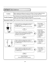
... resistance is open . Check Harness-linking connector. 27 Check it resistance is not sensed. (Drum motor will flash at 0.5 second intervals.) Measurement Condition After turning Dryer Power Off, measure resistance. YES • Door switch Check (Refer to Component testing.) • Check Lamp. (When opening Door, Drum motor and Trouble Symptom Heater...
... resistance is open . Check Harness-linking connector. 27 Check it resistance is not sensed. (Drum motor will flash at 0.5 second intervals.) Measurement Condition After turning Dryer Power Off, measure resistance. YES • Door switch Check (Refer to Component testing.) • Check Lamp. (When opening Door, Drum motor and Trouble Symptom Heater...
Service Manual
Page 30
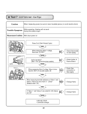
Measurement Condition With dryer power on Valve 1 Igniter Valve 2 Power On & Start (Normal Cycle) NO When measuring Valve 1 voltage, More than DC 90V? (10 sec after Igniter off) YES ...
Measurement Condition With dryer power on Valve 1 Igniter Valve 2 Power On & Start (Normal Cycle) NO When measuring Valve 1 voltage, More than DC 90V? (10 sec after Igniter off) YES ...
Service Manual
Page 37
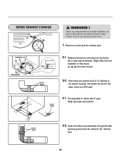
... Pre-assemble 4" elbow with 4" duct. Detach and remove a knockout at the botton, left or right side as desired. (Right Side Vent not available on Gas dryer the order of work. Insert the elbow duct assembly through the side opening and connect the elbow to take gloves and careful exhaust edge. WARNING...
... Pre-assemble 4" elbow with 4" duct. Detach and remove a knockout at the botton, left or right side as desired. (Right Side Vent not available on Gas dryer the order of work. Insert the elbow duct assembly through the side opening and connect the elbow to take gloves and careful exhaust edge. WARNING...


