
Service Manual
Page 1
Website: http://us.lgservice.com Canadian Website: http://lg.ca ELECTRIC & GAS DRYER SERVICE MANUAL CAUTION READ THIS MANUAL CAREFULLY IN ORDER TO PROPERLY DIAGNOSE PROBLEMS AND TO SAFELY PROVIDE QUALITY SERVICE ON THESE DRYERS. MODEL : DLE2516W/DLG2526W/DLE3733 U.S.A.
Website: http://us.lgservice.com Canadian Website: http://lg.ca ELECTRIC & GAS DRYER SERVICE MANUAL CAUTION READ THIS MANUAL CAREFULLY IN ORDER TO PROPERLY DIAGNOSE PROBLEMS AND TO SAFELY PROVIDE QUALITY SERVICE ON THESE DRYERS. MODEL : DLE2516W/DLG2526W/DLE3733 U.S.A.
Service Manual
Page 4
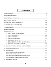
INSTALLATION INSTRUCTIONS 6 4. TEST 3 MOTOR TEST 25 9-4. ELECTRIC MODEL 28 9-7. REPLACEMENT PARTS LIST 43 3 FEATURES AND BENEFITS ...6 3. MOTOR DIAGRAM AND SCHEMATIC 17 7. CONTROL LAYOUT ...18 8. TEST 2 THERMISTOR TEST 24 9-3. ... MODEL 42 13. CHANGE GAS SETTING (NATURAL GAS, PROPANE GAS 30 11. TEST 7 GAS VALVE TEST - CONTENTS 1. WIRING DIAGRAM ...19 9. TEST 1 120V AC ELECTRICAL SUPPLY 21 9-2. TEST 6 HEATER SWITCH TEST - CONTROL PANEL & PLATE ASSEMBLY 39 12-2. COMPONENT TESTING INFORMATION 14 6. CABINET & DOOR ASSEMBLY 40 12-3-1. TEST 4 MOISTURE...
INSTALLATION INSTRUCTIONS 6 4. TEST 3 MOTOR TEST 25 9-4. ELECTRIC MODEL 28 9-7. REPLACEMENT PARTS LIST 43 3 FEATURES AND BENEFITS ...6 3. MOTOR DIAGRAM AND SCHEMATIC 17 7. CONTROL LAYOUT ...18 8. TEST 2 THERMISTOR TEST 24 9-3. ... MODEL 42 13. CHANGE GAS SETTING (NATURAL GAS, PROPANE GAS 30 11. TEST 7 GAS VALVE TEST - CONTENTS 1. WIRING DIAGRAM ...19 9. TEST 1 120V AC ELECTRICAL SUPPLY 21 9-2. TEST 6 HEATER SWITCH TEST - CONTROL PANEL & PLATE ASSEMBLY 39 12-2. COMPONENT TESTING INFORMATION 14 6. CABINET & DOOR ASSEMBLY 40 12-3-1. TEST 4 MOISTURE...
Service Manual
Page 5
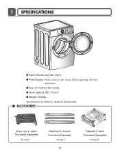
I Dryer capacity: IEC 7.3 cu.ft. I Size: 27 X 29.9 X 38.7 (inch) I ACCESSORIES Dryer rack (1 each) Purchased Separately See page 6 Stacking kit (1 each) Purchased Separately See page 7 4 Pedestal (1 each) Purchased Separately See page 8 1 SPECIFICATIONS I Name: Electric and Gas Dryer I Weight: 126(Ibs) Specifications are subject to the rating label regarding detailed information. I Power supply: Please refer to change by manufacturer.
I Dryer capacity: IEC 7.3 cu.ft. I Size: 27 X 29.9 X 38.7 (inch) I ACCESSORIES Dryer rack (1 each) Purchased Separately See page 6 Stacking kit (1 each) Purchased Separately See page 7 4 Pedestal (1 each) Purchased Separately See page 8 1 SPECIFICATIONS I Name: Electric and Gas Dryer I Weight: 126(Ibs) Specifications are subject to the rating label regarding detailed information. I Power supply: Please refer to change by manufacturer.
Service Manual
Page 6
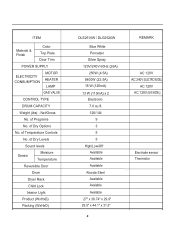
of Dry Options No. Net/Gross No. of Programs No. of Dry Levels Sound levels Sensor Moisture Temperature Reversible Door Drum Dryer Rack Child Lock Interior Light Product (WxHxD) Packing (WxHxD) DLE2516W / DLG2526W Blue White Porcelain Silver Spray 120V/240V 60Hz (.../Off Available Available Available Alcosta Steel Available Avaiable Avaiable 27" x 38.74" x 29.9" 29.5" x 44.1" x 31.3" 5 REMARK AC 120V AC 240V (ELECTRIC MODEL) AC 120V AC 120V (GAS MODEL) Electrode sensor Thermistor of Temperature Controls No. ITEM Material & Finish Color Top Plate Door Trim POWER SUPPLY...
of Dry Options No. Net/Gross No. of Programs No. of Dry Levels Sound levels Sensor Moisture Temperature Reversible Door Drum Dryer Rack Child Lock Interior Light Product (WxHxD) Packing (WxHxD) DLE2516W / DLG2526W Blue White Porcelain Silver Spray 120V/240V 60Hz (.../Off Available Available Available Alcosta Steel Available Avaiable Avaiable 27" x 38.74" x 29.9" 29.5" x 44.1" x 31.3" 5 REMARK AC 120V AC 240V (ELECTRIC MODEL) AC 120V AC 120V (GAS MODEL) Electrode sensor Thermistor of Temperature Controls No. ITEM Material & Finish Color Top Plate Door Trim POWER SUPPLY...
Service Manual
Page 10
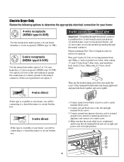
...the terminal block(hooked end facing rightward) and pinch the hook together and screw tightly. Make a 5 inch of power cord to determine the appropriate electrical connection for (1) new branch-circuit installations, (2) mobile homes, and (3) recreational vehicles, and (4) areas where local codes prohibit grounding through the neutral.... 3. Use option 2 if local codes and ordinances permit the connection of the wire under option 2 or 3 if your home. Electric Dryer Only Review the following options to center terminal block screw. 2. Connect neutral wire(white) of ground wire bared.
...the terminal block(hooked end facing rightward) and pinch the hook together and screw tightly. Make a 5 inch of power cord to determine the appropriate electrical connection for (1) new branch-circuit installations, (2) mobile homes, and (3) recreational vehicles, and (4) areas where local codes prohibit grounding through the neutral.... 3. Use option 2 if local codes and ordinances permit the connection of the wire under option 2 or 3 if your home. Electric Dryer Only Review the following options to center terminal block screw. 2. Connect neutral wire(white) of ground wire bared.
Service Manual
Page 20
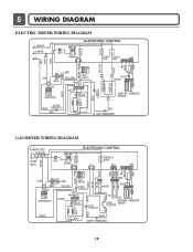
LIMIT THERMOSTAT GAS DRYER WIRING DIAGRAM POWER CORD L1 BLACK N WHITE GN/YL WHITE 1 WH1 TRANS BL2 3 1 ELECTRONIC CONTROL YL2 1 3 TAB RELAY BLACK BL3 123 NA6 6 5 4321 RED PINK ... HI-LIMIT THERMOSTAT WHITE DC VALVE1 DC VALVE2 MOISTURE THERMISTOR FLAME SENSOR DETECTOR CENTRIFUGAL SWITCH RED WHITE NC NO GRAY SAFETY THERMOSTAT 19 8 WIRING DIAGRAM ELECTRIC DRYER WIRING DIAGRAM L1 BLACK N WHITE L2 ELECTRONIC CONTROL 1 WH1 TRANS BL2 3 1 TAB RELAY TAB RELAY BLACK WHITE NA6 6 5 432 1 RED WHITE BACK BLUE ORANGE RED...
LIMIT THERMOSTAT GAS DRYER WIRING DIAGRAM POWER CORD L1 BLACK N WHITE GN/YL WHITE 1 WH1 TRANS BL2 3 1 ELECTRONIC CONTROL YL2 1 3 TAB RELAY BLACK BL3 123 NA6 6 5 4321 RED PINK ... HI-LIMIT THERMOSTAT WHITE DC VALVE1 DC VALVE2 MOISTURE THERMISTOR FLAME SENSOR DETECTOR CENTRIFUGAL SWITCH RED WHITE NC NO GRAY SAFETY THERMOSTAT 19 8 WIRING DIAGRAM ELECTRIC DRYER WIRING DIAGRAM L1 BLACK N WHITE L2 ELECTRONIC CONTROL 1 WH1 TRANS BL2 3 1 TAB RELAY TAB RELAY BLACK WHITE NA6 6 5 432 1 RED WHITE BACK BLUE ORANGE RED...
Service Manual
Page 22
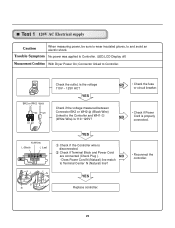
... line match to Controller. NO • Check the fuse or circuit breaker. • Check if Power NO Cord is disconnected. Test 1 120V AC Electrical supply Caution When measuring power, be sure to wear insulated gloves, to Controller. (LED,LCD Display off) Measurement Condition With... Dryer Power On; Trouble Symptom No power was applied to and avoid an electric shock. Check if Terminal Block and Power Cord are connected (Check Plug ). YES Check if the voltage ...
... line match to Controller. NO • Check the fuse or circuit breaker. • Check if Power NO Cord is disconnected. Test 1 120V AC Electrical supply Caution When measuring power, be sure to wear insulated gloves, to Controller. (LED,LCD Display off) Measurement Condition With... Dryer Power On; Trouble Symptom No power was applied to and avoid an electric shock. Check if Terminal Block and Power Cord are connected (Check Plug ). YES Check if the voltage ...
Service Manual
Page 23
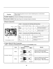
...off on Heater1 and Heater2. Low Extra Low on off Temperature Control below 47 4°C. Turn on Heater1. White Tab Relay) 22 Measurement Condition With Dryer Power On; Trans ❈ PCB ASSEMBLY LAYOUT < Table 2 > : Connection of the Tab Relay with Burner (Gas) High Mid High Medium Low... Symptom Check the Tab Relays Connection properly. Only Turn on Burner Temperature Control below 52 4°C. Connector linked to and avoid an electric shock. Turn on Temperature Control below 70 4°C. Status Mode Of The Connection < Table1 > : Connection of Tab Relay with ...
...off on Heater1 and Heater2. Low Extra Low on off Temperature Control below 47 4°C. Turn on Heater1. White Tab Relay) 22 Measurement Condition With Dryer Power On; Trans ❈ PCB ASSEMBLY LAYOUT < Table 2 > : Connection of the Tab Relay with Burner (Gas) High Mid High Medium Low... Symptom Check the Tab Relays Connection properly. Only Turn on Burner Temperature Control below 52 4°C. Connector linked to and avoid an electric shock. Turn on Temperature Control below 70 4°C. Status Mode Of The Connection < Table1 > : Connection of Tab Relay with ...
Service Manual
Page 27
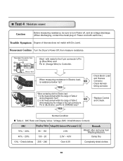
...'s Pin (BLUE wire) and Pin (ORANGE wire)? Short with Dry Level. Is the measurement within the range of Table 2 NO when measuring the voltage in Electric load, is resistance below 1Ω? NO YES Damping cloth When contacting cloth to Controller. YES • Check Electro Load and Harness Connector. • Check Harnesslinking... of dryness does not match with metal to the 6 pin connector's Pin (Blue Wire) and Pin (Orange Wire) to Electro load: 1. Measurement Condition Turn the Dryer's Power Off, then measure resistance.
...'s Pin (BLUE wire) and Pin (ORANGE wire)? Short with Dry Level. Is the measurement within the range of Table 2 NO when measuring the voltage in Electric load, is resistance below 1Ω? NO YES Damping cloth When contacting cloth to Controller. YES • Check Electro Load and Harness Connector. • Check Harnesslinking... of dryness does not match with metal to the 6 pin connector's Pin (Blue Wire) and Pin (Orange Wire) to Electro load: 1. Measurement Condition Turn the Dryer's Power Off, then measure resistance.
Service Manual
Page 30
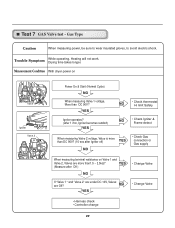
... YES • Change Valve • Harness check • Controller change 29 Gas Type Caution When measuring power, be sure to wear insulated gloves, to avoid electric shock. Measurement Condition With dryer power on Valve 1 and Valve 2, Valves are Off? Test 7 GAS Valve test - Trouble Symptom While operating, Heating will not work.
... YES • Change Valve • Harness check • Controller change 29 Gas Type Caution When measuring power, be sure to wear insulated gloves, to avoid electric shock. Measurement Condition With dryer power on Valve 1 and Valve 2, Valves are Off? Test 7 GAS Valve test - Trouble Symptom While operating, Heating will not work.


