Service Manual
Page 11
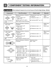
...type 5. Measure resistance of the following terminal : "COM - Idler switch Measure resistance of the following terminal 1) Door switch knob : open Resistance value < 1Ω 2. Thermal cut off. "NC" (1-3) Terminal : "COM" - Resistance value ∞ Resistance value < 5Ω ...Measure resistance of terminal Resistance value : to terminal Open at 257 ± 9°F (125 ± 5°C) Close at 149 ± 9°F (65 ± 5°C) Same shape as Outlet Thermostat...
...type 5. Measure resistance of the following terminal : "COM - Idler switch Measure resistance of the following terminal 1) Door switch knob : open Resistance value < 1Ω 2. Thermal cut off. "NC" (1-3) Terminal : "COM" - Resistance value ∞ Resistance value < 5Ω ...Measure resistance of terminal Resistance value : to terminal Open at 257 ± 9°F (125 ± 5°C) Close at 149 ± 9°F (65 ± 5°C) Same shape as Outlet Thermostat...
Service Manual
Page 12
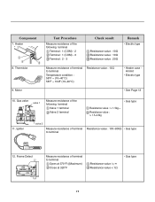
... value : 10Ω • Heater case Hi limit • Electric type • See Page 13 10. Gas valve valve 1 Measure resistance of terminal to terminal Open at 370°F ((Maximum) Close at 320°F Resistance value ∞ Resistance value < 1Ω • Gas type 11 Igniter valve 2 Measure resistance of the following...
... value : 10Ω • Heater case Hi limit • Electric type • See Page 13 10. Gas valve valve 1 Measure resistance of terminal to terminal Open at 370°F ((Maximum) Close at 320°F Resistance value ∞ Resistance value < 1Ω • Gas type 11 Igniter valve 2 Measure resistance of the following...

Service Manual
Page 13
...reset) • Check Top Marking : N95 13. Outlet Thermostat (Manual reset) • Check Top Marking : N100 Test Procedure Measure resistance of terminal to terminal Open at 203 ± 7°F (95 ± 5°C) Close at 158 ± 9°F (70 ± 5°C) Check result Resistance value ∞...Continuity < 1Ω Remark • Gas type • Gas funnel Measure resistance of terminal to terminal Open at 212 ± 12°F (100 ± 7°C) Manual reset If thermal fuse is open must be replaced Resistance value ∞ Continuity < 1Ω • Gas type • Gas ...
...reset) • Check Top Marking : N95 13. Outlet Thermostat (Manual reset) • Check Top Marking : N100 Test Procedure Measure resistance of terminal to terminal Open at 203 ± 7°F (95 ± 5°C) Close at 158 ± 9°F (70 ± 5°C) Check result Resistance value ∞...Continuity < 1Ω Remark • Gas type • Gas funnel Measure resistance of terminal to terminal Open at 212 ± 12°F (100 ± 7°C) Manual reset If thermal fuse is open must be replaced Resistance value ∞ Continuity < 1Ω • Gas type • Gas ...
Service Manual
Page 17
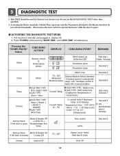
... Pressing the "START/PAUSE" button CHECKING ACTION DISPLAY CHECKING POINT REMARK None Electric control & Temperature sensor Won't power up Defective LED Thermistor open ) ACTIVATING THE DIAGNOSTIC TEST MODE 1. Do not use this DIAGNOSTIC TEST other than specified. 2. The display number is closed. + Lamp ...sound See test 3 See test 4 Gas valve See test 7 See test 5 Off automatically after 5 minutes During check, If the door is open Thermistor close See test 1 Display : See page See test 2 Once Twice 3 times Motor Motor runs 70 ~ 237 Measured Moisture Value. ...
... Pressing the "START/PAUSE" button CHECKING ACTION DISPLAY CHECKING POINT REMARK None Electric control & Temperature sensor Won't power up Defective LED Thermistor open ) ACTIVATING THE DIAGNOSTIC TEST MODE 1. Do not use this DIAGNOSTIC TEST other than specified. 2. The display number is closed. + Lamp ...sound See test 3 See test 4 Gas valve See test 7 See test 5 Off automatically after 5 minutes During check, If the door is open Thermistor close See test 1 Display : See page See test 2 Once Twice 3 times Motor Motor runs 70 ~ 237 Measured Moisture Value. ...
Service Manual
Page 22
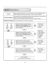
...After turning Dryer Power Off, measure resistance. YES • Door switch Check (Refer to Component testing.) • Check Lamp. (When opening Door, Drum motor and Trouble Symptom Heater run continuously; Check if resistance is 300~60Ω between "BL2- Display will not operate....Measure while Door is closed . " (White wire) after taking Connector WH3, BL2 out from Controller. Check Harness-linking connector. 21 Door Close is open . Measure while Door is closed . " (White wire) and "RD3- " (Black wire) NO Connector WH3, RD3 after YES taking WH3,...
...After turning Dryer Power Off, measure resistance. YES • Door switch Check (Refer to Component testing.) • Check Lamp. (When opening Door, Drum motor and Trouble Symptom Heater run continuously; Check if resistance is 300~60Ω between "BL2- Display will not operate....Measure while Door is closed . " (White wire) after taking Connector WH3, BL2 out from Controller. Check Harness-linking connector. 21 Door Close is open . Measure while Door is closed . " (White wire) and "RD3- " (Black wire) NO Connector WH3, RD3 after YES taking WH3,...
Service Manual
Page 25
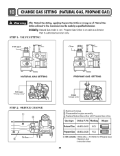
... contents : Orifice (Dia. = 1.613mm, for Propane Gas) : Replace Label : Instruction sheet 24 Propane Gas Orifice is set. Disassemble the pipe assembly. STEP 1 : VALVE SETTING Full open "Change screw" STEP 2 : ORIFICE CHANGE Orifice Close "Change screw" Remove 2 screws. 10 CHANGE GAS SETTING (NATURAL GAS, PROPANE GAS) ! Warning After Natural Gas Setting, applying...
... contents : Orifice (Dia. = 1.613mm, for Propane Gas) : Replace Label : Instruction sheet 24 Propane Gas Orifice is set. Disassemble the pipe assembly. STEP 1 : VALVE SETTING Full open "Change screw" STEP 2 : ORIFICE CHANGE Orifice Close "Change screw" Remove 2 screws. 10 CHANGE GAS SETTING (NATURAL GAS, PROPANE GAS) ! Warning After Natural Gas Setting, applying...
Service Manual
Page 26
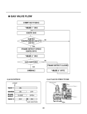
GAS VALVE FLOW START KEY PUSH "VALVE 1" ON IGNITE ON IGNITE TEMPERATURE ABOUT 370"F YES FRAME DETECT OPEN IGNITE OFF "VALVE 2" ON GAS IGNITION YES DRYING NO NO FRAME DETECT CLOSE "VALVE 2" OFF GAS IGNITION START VALVE 1 IGNITER FRAME DETECT VALVE 2 ON ON CLOSE OFF OFF OPEN ON GAS IGNITION GAS VALVE STRUCTURE 25
GAS VALVE FLOW START KEY PUSH "VALVE 1" ON IGNITE ON IGNITE TEMPERATURE ABOUT 370"F YES FRAME DETECT OPEN IGNITE OFF "VALVE 2" ON GAS IGNITION YES DRYING NO NO FRAME DETECT CLOSE "VALVE 2" OFF GAS IGNITION START VALVE 1 IGNITER FRAME DETECT VALVE 2 ON ON CLOSE OFF OFF OPEN ON GAS IGNITION GAS VALVE STRUCTURE 25
Service Manual
Page 27
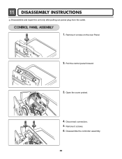
Disassemble the controller assembly. 26 Remove 3 screws on the rear Panel. 2. Open the cover protect. 4. Disconnect connectors. 5. 11 DISASSEMBLY INSTRUCTIONS Disassemble and repair the unit only after pulling out power plug from the outlet. 1. Remove 5 screws. 6. Pull the control panel forward. 3.
Disassemble the controller assembly. 26 Remove 3 screws on the rear Panel. 2. Open the cover protect. 4. Disconnect connectors. 5. 11 DISASSEMBLY INSTRUCTIONS Disassemble and repair the unit only after pulling out power plug from the outlet. 1. Remove 5 screws. 6. Pull the control panel forward. 3.

Service Manual
Page 28
Push backward using an opener and lift the top plate. 1. Pull the Cover Cabinet. 5. Disconnect the door switch connector. 27 Remove 2 screws form upper side. 4. Open the top plate. 2. Open the door, Remove 2 screws. 3. 7cm 7cm 1.
Push backward using an opener and lift the top plate. 1. Pull the Cover Cabinet. 5. Disconnect the door switch connector. 27 Remove 2 screws form upper side. 4. Open the top plate. 2. Open the door, Remove 2 screws. 3. 7cm 7cm 1.
Service Manual
Page 29
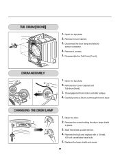
... door. 2. Disassemble the Tub Drum [Front]. -1 1. Remove the bulb and replace with a 15 watt, 120 volt candelabra-base bulb. 5. Open the top plate. -1 2. Carefully remove Drum out through front of dryer. 1. Remove 4 screws. 5. Disengage belt from motor and idler pulleys. 4. Remove the screw holding the ... lamp shield in place. 3. Replace the lamp shield and screw. 28 Remove the Cover Cabinet and Tub drum [front]. -2 3. Slide the shield up and remove. 4. Open the top plate. 2. Remove Cover Cabinet. 3. 1.
... door. 2. Disassemble the Tub Drum [Front]. -1 1. Remove the bulb and replace with a 15 watt, 120 volt candelabra-base bulb. 5. Open the top plate. -1 2. Carefully remove Drum out through front of dryer. 1. Remove 4 screws. 5. Disengage belt from motor and idler pulleys. 4. Remove the screw holding the ... lamp shield in place. 3. Replace the lamp shield and screw. 28 Remove the Cover Cabinet and Tub drum [front]. -2 3. Slide the shield up and remove. 4. Open the top plate. 2. Remove Cover Cabinet. 3. 1.
Service Manual
Page 30
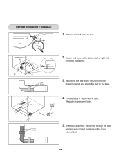
1. Reconnect the new duct[11 in(28cm)] to the blower housing, and attach the duct to the dryer internal duct. 29 Remove screw & exhaust duct. Detach and remove the bottom, left or right side knockout as desired. Pre-assemble 4" elbow with 4" duct. DUCT TAPE 3. DUCT TAPE 4. Wrap duct tape around joint. PORTION "A" 2. DUCT TAPE 5. Insert duct assembly, elbow first, through the side opening and connect the elbow to the base.
1. Reconnect the new duct[11 in(28cm)] to the blower housing, and attach the duct to the dryer internal duct. 29 Remove screw & exhaust duct. Detach and remove the bottom, left or right side knockout as desired. Pre-assemble 4" elbow with 4" duct. DUCT TAPE 3. DUCT TAPE 4. Wrap duct tape around joint. PORTION "A" 2. DUCT TAPE 5. Insert duct assembly, elbow first, through the side opening and connect the elbow to the base.
Service Manual
Page 31
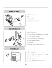
Remove the Cover Cabinet and Tub Drum [Front]. 3. Remove the bolt and washer. 6. Pull the fan. 7. Disconnect electro sensor. 1. Remove the Drum assembly. 4. Open the top plate. 2. Remove 7 screws. 5. Pull the Tub Drum [Rear] towards the front. 30 Open the top plate. 2. Remove 2 screws and cover(Air guide). 5. Remove the Drum assembly. 4. Remove the filter. 2. Remove the Cover Cabinet and Tub Drum [Front]. 3. Pull the grill. 4. Disconnect the motor clamp and motor. 1. Remove 3 screws. 3. 1.
Remove the Cover Cabinet and Tub Drum [Front]. 3. Remove the bolt and washer. 6. Pull the fan. 7. Disconnect electro sensor. 1. Remove the Drum assembly. 4. Open the top plate. 2. Remove 7 screws. 5. Pull the Tub Drum [Rear] towards the front. 30 Open the top plate. 2. Remove 2 screws and cover(Air guide). 5. Remove the Drum assembly. 4. Remove the filter. 2. Remove the Cover Cabinet and Tub Drum [Front]. 3. Pull the grill. 4. Disconnect the motor clamp and motor. 1. Remove 3 screws. 3. 1.
Service Manual
Page 32
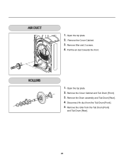
Remove the Cover Cabinet. 3. Open the top plate. 2. Disconnect Air duct from the Tub Drum [Front] and Tub Drum [Rear]. 31 Remove the Cover Cabinet and Tub Drum [Front]. 3. Remove the Drum assembly and Tub Drum [Rear]. 4. Remove filter and 2 screws. 4. Pull the air duct towards the front. 1. Open the top plate. 2. Remove the roller from the Tub Drum [Front]. 5. 1.
Remove the Cover Cabinet. 3. Open the top plate. 2. Disconnect Air duct from the Tub Drum [Front] and Tub Drum [Rear]. 31 Remove the Cover Cabinet and Tub Drum [Front]. 3. Remove the Drum assembly and Tub Drum [Rear]. 4. Remove filter and 2 screws. 4. Pull the air duct towards the front. 1. Open the top plate. 2. Remove the roller from the Tub Drum [Front]. 5. 1.


