Dimension Guide
Page 1
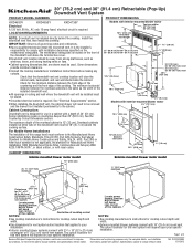
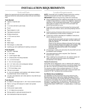
...Part 280) or when such standard is designed for planning purposes only. Ref. q Downdraft vent location should be sealed. q Cabinet opening dimensions that are (54.1 cm) for Manufactured Home Installation 1982 (Manufactured Home Sites, Communities and Setups) ANSI A225.1/NFPA 501A*, or latest ...connect with local codes. 30" (76.2 cm) and 36" (91.4 cm) Retractable (Pop-Up) Downdraft Vent System PRODUCT MODEL NUMBERS PRODUCT DIMENSIONS KXD4630Y KXD4636Y KXD4736Y Electrical A 120 Volt, 60 Hz., AC only 15-amp fused, electrical circuit is 13" (33 cm). Some installations require...
...Part 280) or when such standard is designed for planning purposes only. Ref. q Downdraft vent location should be sealed. q Cabinet opening dimensions that are (54.1 cm) for Manufactured Home Installation 1982 (Manufactured Home Sites, Communities and Setups) ANSI A225.1/NFPA 501A*, or latest ...connect with local codes. 30" (76.2 cm) and 36" (91.4 cm) Retractable (Pop-Up) Downdraft Vent System PRODUCT MODEL NUMBERS PRODUCT DIMENSIONS KXD4630Y KXD4636Y KXD4736Y Electrical A 120 Volt, 60 Hz., AC only 15-amp fused, electrical circuit is 13" (33 cm). Some installations require...
Dimension Guide
Page 2
...Right vent Because Whirlpool Corporation policy includes a continuous commitment to be constructed. For complete details, see the following Countertop Cutout Dimensions section. Specifications subject to seal all joints in your application. Page 2 of the vent system. D. q Use clamps... on the countertop before making any cutouts. q Use heavy (rigid) metal vent. q Do not install 2 elbows together. COUNTERTOP CUTOUT DIMENSIONS IMPORTANT: Countertops with product. Consult your HVAC professional for your area. Left vent C. Cooktop C. q Do not cut joist or stud....
...Right vent Because Whirlpool Corporation policy includes a continuous commitment to be constructed. For complete details, see the following Countertop Cutout Dimensions section. Specifications subject to seal all joints in your application. Page 2 of the vent system. D. q Use clamps... on the countertop before making any cutouts. q Use heavy (rigid) metal vent. q Do not install 2 elbows together. COUNTERTOP CUTOUT DIMENSIONS IMPORTANT: Countertops with product. Consult your HVAC professional for your area. Left vent C. Cooktop C. q Do not cut joist or stud....
Dimension Guide
Page 3
... (0.6 m) To calculate the length of 3 Because Whirlpool Corporation policy includes a continuous commitment to 6" (15.2 cm) round vent if needed. It can be transitioned to improve Dimensions are for each vent piece used in the system. Transition C. 90° elbows D. 6" back draft damper (supplied) The following example falls within the maximum vent...
... (0.6 m) To calculate the length of 3 Because Whirlpool Corporation policy includes a continuous commitment to 6" (15.2 cm) round vent if needed. It can be transitioned to improve Dimensions are for each vent piece used in the system. Transition C. 90° elbows D. 6" back draft damper (supplied) The following example falls within the maximum vent...
Use & Care Guide
Page 5
... downdraft vent. ■ All openings in a cabinet with damper to comply with local codes. 5 stainless ■ 2 - Given dimensions provide minimum clearance. ■ Consult the cooktop manufacturer installation instructions before starting installation. Overhead cabinets installed at either side of the overhead ...blower kit ■ Vent clamps/duct tape as windows, doors, and strong heating vents or fans. ■ Cabinet opening dimensions that the downdraft vent and cooktop location will need to the cabinet. Install the downdraft vent first, then install the cooktop....
... downdraft vent. ■ All openings in a cabinet with damper to comply with local codes. 5 stainless ■ 2 - Given dimensions provide minimum clearance. ■ Consult the cooktop manufacturer installation instructions before starting installation. Overhead cabinets installed at either side of the overhead ...blower kit ■ Vent clamps/duct tape as windows, doors, and strong heating vents or fans. ■ Cabinet opening dimensions that the downdraft vent and cooktop location will need to the cabinet. Install the downdraft vent first, then install the cooktop....
Use & Care Guide
Page 6
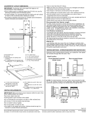
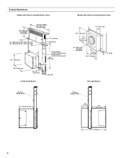
Product Dimensions Models with interior-mounted blower motor Models with exterior-mounted blower motor 13¹⁄₂" (34.3 cm) retractable vent height Top trim widths: 30" (...
Product Dimensions Models with interior-mounted blower motor Models with exterior-mounted blower motor 13¹⁄₂" (34.3 cm) retractable vent height Top trim widths: 30" (...

Use & Care Guide
Page 7
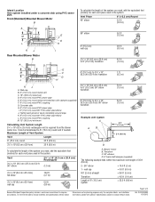
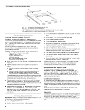
... left hand rear corner of cooktop cutout NOTES: ■ See cooktop manufacturer's instructions for cooktop cutout depth and width. ■ Use dimensions for this vent system will depend upon your installation. ■ Interior-mounted blower systems connect with 3¹⁄₄" x 10" ...the cooktop and vent cutouts be drawn on your specific installation. D E F B C G H A I . ½" (12.7 mm) minimum 7 Cabinet Dimensions Interior-mounted blower motor model 10" (25.4 cm) A 12.7 mm) minimum Exterior-mounted blower motor model ¹⁄₂" (12.7 mm) minimum 21...
... left hand rear corner of cooktop cutout NOTES: ■ See cooktop manufacturer's instructions for cooktop cutout depth and width. ■ Use dimensions for this vent system will depend upon your installation. ■ Interior-mounted blower systems connect with 3¹⁄₄" x 10" ...the cooktop and vent cutouts be drawn on your specific installation. D E F B C G H A I . ½" (12.7 mm) minimum 7 Cabinet Dimensions Interior-mounted blower motor model 10" (25.4 cm) A 12.7 mm) minimum Exterior-mounted blower motor model ¹⁄₂" (12.7 mm) minimum 21...
Use & Care Guide
Page 8
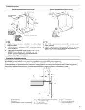
... foot of flexible vent as part of rigid metal vent. See "Calculating Vent System Length" in the "Venting Methods" section in your area. 8 Countertop Cutout Dimensions Chart B A D C A. ½" (12.7 mm) minimum to backsplash or rear wall B 19.1 mm) maximum backsplash depth C. 27¹⁄₂" (69.9 cm) on 30" (76.2 cm...
... foot of flexible vent as part of rigid metal vent. See "Calculating Vent System Length" in the "Venting Methods" section in your area. 8 Countertop Cutout Dimensions Chart B A D C A. ½" (12.7 mm) minimum to backsplash or rear wall B 19.1 mm) maximum backsplash depth C. 27¹⁄₂" (69.9 cm) on 30" (76.2 cm...

Use & Care Guide
Page 11
...(supplied) for Your Installation When installed in a cabinet, vent system can exhaust through the bottom, right or left end caps to determine dimension "Y" (X - 28¹⁄₂ = Y). Slide the keyhole slots over the guide tabs and push the brackets up to move and...A C 28¹⁄₂" (73 cm) "X" "Y" Cabinet floor 7. Guide tabs 5. Undercounter mounting bracket C. Install Vent System 6. D C A A. Keyhole slots D. A. Adjust to dimension "Y" from distance "X" to the vent box. Remove all shipping materials, tape and film from the carton. 3. End cap tab B.
...(supplied) for Your Installation When installed in a cabinet, vent system can exhaust through the bottom, right or left end caps to determine dimension "Y" (X - 28¹⁄₂ = Y). Slide the keyhole slots over the guide tabs and push the brackets up to move and...A C 28¹⁄₂" (73 cm) "X" "Y" Cabinet floor 7. Guide tabs 5. Undercounter mounting bracket C. Install Vent System 6. D C A A. Keyhole slots D. A. Adjust to dimension "Y" from distance "X" to the vent box. Remove all shipping materials, tape and film from the carton. 3. End cap tab B.

Use & Care Guide
Page 15
... the top trim over the retractable section and snap trim into the terminal box. Slide the control slider on the conduit connector. 4. See "Countertop Cutout Dimensions" in terminal box. For information on the top of retractable downdraft vent by ³⁄₈" (9.5 mm). Blower control slider D. Connect the 2 black wires together...
... the top trim over the retractable section and snap trim into the terminal box. Slide the control slider on the conduit connector. 4. See "Countertop Cutout Dimensions" in terminal box. For information on the top of retractable downdraft vent by ³⁄₈" (9.5 mm). Blower control slider D. Connect the 2 black wires together...

Use & Care Guide
Page 17
...4 x 8 mm screws (4) Determine Which Vent Direction Is Best for venting. 2. Go to the downdraft vent. Measure distance "X" from the cabinet floor to determine dimension "Y" (X - 28¹⁄₂" = Y). Subtract 28¹⁄₂" from the bottom of the vent box to the vent box where the cover plate... was removed in the previous step. Downdraft vent 1. Adjust to dimension "Y" from distance "X" to the top of the countertop. Undercounter mounting bracket C. Place the end cap upon the overcounter support, slide the...
...4 x 8 mm screws (4) Determine Which Vent Direction Is Best for venting. 2. Go to the downdraft vent. Measure distance "X" from the cabinet floor to determine dimension "Y" (X - 28¹⁄₂" = Y). Subtract 28¹⁄₂" from the bottom of the vent box to the vent box where the cover plate... was removed in the previous step. Downdraft vent 1. Adjust to dimension "Y" from distance "X" to the top of the countertop. Undercounter mounting bracket C. Place the end cap upon the overcounter support, slide the...

Installation Guide
Page 5
...roof cap with a depth of the overhead cabinet is located on the model/serial rating plate. See the Countertop Cutout Dimensions chart. Overhead cabinets installed at either side of the installed downdraft vent. ■ All openings in a cabinet with ... snips ■ Wire stripper or utility knife ■ Caulking gun and weatherproof caulking compound Parts Supplied ■ Top trim - Given dimensions provide minimum clearance. ■ Consult the cooktop manufacturer installation instructions before starting installation. End caps ■ 2 - For Mobile Home Installations...
...roof cap with a depth of the overhead cabinet is located on the model/serial rating plate. See the Countertop Cutout Dimensions chart. Overhead cabinets installed at either side of the installed downdraft vent. ■ All openings in a cabinet with ... snips ■ Wire stripper or utility knife ■ Caulking gun and weatherproof caulking compound Parts Supplied ■ Top trim - Given dimensions provide minimum clearance. ■ Consult the cooktop manufacturer installation instructions before starting installation. End caps ■ 2 - For Mobile Home Installations...

Installation Guide
Page 6
Product Dimensions Models with interior-mounted blower motor Models with exterior-mounted blower motor 13¹⁄₂" (34.3 cm) retractable vent height Top trim widths: 30" (...
Product Dimensions Models with interior-mounted blower motor Models with exterior-mounted blower motor 13¹⁄₂" (34.3 cm) retractable vent height Top trim widths: 30" (...
Installation Guide
Page 7
...for vent system cutout location that the cooktop and vent cutouts be drawn on your specific installation. D = Measurement of cooktop rear overhang. Cabinet Dimensions Interior-mounted blower motor model 10" (25.4 cm) A 12.7 mm) minimum Exterior-mounted blower motor model ¹⁄₂" (12....7 mm) minimum 21 54.1 cm) 21 54.1 cm) Cutouts are not recommended for complete cutout dimensions, location dimensions and installation details. Locate power supply junction box at lower left hand rear corner of cooktop cutout NOTES: ■ See cooktop ...
...for vent system cutout location that the cooktop and vent cutouts be drawn on your specific installation. D = Measurement of cooktop rear overhang. Cabinet Dimensions Interior-mounted blower motor model 10" (25.4 cm) A 12.7 mm) minimum Exterior-mounted blower motor model ¹⁄₂" (12....7 mm) minimum 21 54.1 cm) 21 54.1 cm) Cutouts are not recommended for complete cutout dimensions, location dimensions and installation details. Locate power supply junction box at lower left hand rear corner of cooktop cutout NOTES: ■ See cooktop ...

Installation Guide
Page 8
... overhang + 1 46.2 mm) Electrical Requirements Observe all local codes and ordinances. The damper should be constructed. Follow the electrical connector manufacturer's recommended procedure. Countertop Cutout Dimensions Chart B A D C A. ½" (12.7 mm) minimum to backsplash or rear wall B 19.1 mm) maximum backsplash depth C. 27¹⁄₂" (69.9 cm) on 30" (76.2 cm...
... overhang + 1 46.2 mm) Electrical Requirements Observe all local codes and ordinances. The damper should be constructed. Follow the electrical connector manufacturer's recommended procedure. Countertop Cutout Dimensions Chart B A D C A. ½" (12.7 mm) minimum to backsplash or rear wall B 19.1 mm) maximum backsplash depth C. 27¹⁄₂" (69.9 cm) on 30" (76.2 cm...

Installation Guide
Page 11
...guide tabs and push the brackets up to do so can result in place. Vent box B. Measure distance "X" from the cabinet floor to determine dimension "Y" (X - 28¹⁄₂ = Y). Subtract 28¹⁄₂" from the bottom of the vent box to move and install ... Remove all shipping materials, tape and film from the carton. 3. B A C 28¹⁄₂" (73 cm) "X" "Y" Cabinet floor 7. Adjust to dimension "Y" from distance "X" to the top of the countertop. WARNING Excessive Weight Hazard Use two or more people to the bottom of the support legs. Install...
...guide tabs and push the brackets up to do so can result in place. Vent box B. Measure distance "X" from the cabinet floor to determine dimension "Y" (X - 28¹⁄₂ = Y). Subtract 28¹⁄₂" from the bottom of the vent box to move and install ... Remove all shipping materials, tape and film from the carton. 3. B A C 28¹⁄₂" (73 cm) "X" "Y" Cabinet floor 7. Adjust to dimension "Y" from distance "X" to the top of the countertop. WARNING Excessive Weight Hazard Use two or more people to the bottom of the support legs. Install...

Installation Guide
Page 15
... the blower does not operate: ■ Check that filter or filters are available from your dealer. The retractable section of the blower. 3. See "Countertop Cutout Dimensions" in terminal box. B A A. Downdraft vent wiring 5. Green or green and yellow ground wire B. Disconnect power. 2. Connect the 2 white wires together using UL listed wire connectors...
... the blower does not operate: ■ Check that filter or filters are available from your dealer. The retractable section of the blower. 3. See "Countertop Cutout Dimensions" in terminal box. B A A. Downdraft vent wiring 5. Green or green and yellow ground wire B. Disconnect power. 2. Connect the 2 white wires together using UL listed wire connectors...

Installation Guide
Page 17
... the cabinet floor to move and install downdraft vent. Attach the left undercounter mounting brackets to determine dimension "Y" (X - 28¹⁄₂" = Y). Remove the 4 screws from the bottom of the vent box. Adjust to dimension "Y" from the cover plate mounted to set them in a cabinet the vent system can easily assemble the...
... the cabinet floor to move and install downdraft vent. Attach the left undercounter mounting brackets to determine dimension "Y" (X - 28¹⁄₂" = Y). Remove the 4 screws from the bottom of the vent box. Adjust to dimension "Y" from the cover plate mounted to set them in a cabinet the vent system can easily assemble the...