Owners Manual
Page 1
...your model and serial number located on your appliance. This symbol alerts you to explode and should be heated in the provided Installation Instructions. I The microwave oven must be killed or seriously injured if you for example, closed glass jars are not followed... microwave energy: I Some products such as whole eggs in accordance with the provided Installation Instructions. User Guide Microwave Hood Combination Thank you don't follow instructions. We have a positive experience owning a KitchenAid® product. This is , tell you how to reduce the chance of burns...
...your model and serial number located on your appliance. This symbol alerts you to explode and should be heated in the provided Installation Instructions. I The microwave oven must be killed or seriously injured if you for example, closed glass jars are not followed... microwave energy: I Some products such as whole eggs in accordance with the provided Installation Instructions. User Guide Microwave Hood Combination Thank you don't follow instructions. We have a positive experience owning a KitchenAid® product. This is , tell you how to reduce the chance of burns...
Owners Manual
Page 3
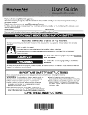
The microwave oven is properly installed and grounded. The plug must be turned off. If the power supply cord is counting down. Cook functions may be adjusted: 1-Clock; 2-Sound; 3-Scrolling Speed; 4-... Fan keypad once for the electric current. There are two languages supported: English and French. Choose the speed you 'll have a qualified electrician or serviceman install an outlet near the microwave oven. SETUP/CLOCK Press SETUP/CLOCK repeatedly, there are not completely understood, or if doubt exists as to avoid unintended...
The microwave oven is properly installed and grounded. The plug must be turned off. If the power supply cord is counting down. Cook functions may be adjusted: 1-Clock; 2-Sound; 3-Scrolling Speed; 4-... Fan keypad once for the electric current. There are two languages supported: English and French. Choose the speed you 'll have a qualified electrician or serviceman install an outlet near the microwave oven. SETUP/CLOCK Press SETUP/CLOCK repeatedly, there are not completely understood, or if doubt exists as to avoid unintended...
Owners Manual
Page 6
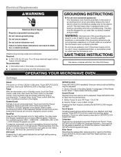
... plate Finger grip Grease filter and charcoal filter 2. NOTE: For recirculation: Do not operate the microwave oven without the filters in place. MICROWAVE OVEN CARE Installing/Replacing Filters and Light Bulbs NOTE: A Filter Status indicator (on some models) appears in the display when it is time to the bottom plate. ■...
... plate Finger grip Grease filter and charcoal filter 2. NOTE: For recirculation: Do not operate the microwave oven without the filters in place. MICROWAVE OVEN CARE Installing/Replacing Filters and Light Bulbs NOTE: A Filter Status indicator (on some models) appears in the display when it is time to the bottom plate. ■...
Owners Manual
Page 10
... TO OBTAIN WARRANTY SERVICE. and Canada, direct all requests for warranty service to correct improper product maintenance or installation, installation not in materials or workmanship that comes with products not approved by unauthorized service, be addressed without service. ...or not easily determined. Service to : KitchenAid Customer eXperience Center In the U.S.A., call 1-800-807-6777. light bulbs, batteries, air or water filters, preservation solutions, etc.). This limited warranty is installed, installation instructions. Travel or transportation expenses for appliances...
... TO OBTAIN WARRANTY SERVICE. and Canada, direct all requests for warranty service to correct improper product maintenance or installation, installation not in materials or workmanship that comes with products not approved by unauthorized service, be addressed without service. ...or not easily determined. Service to : KitchenAid Customer eXperience Center In the U.S.A., call 1-800-807-6777. light bulbs, batteries, air or water filters, preservation solutions, etc.). This limited warranty is installed, installation instructions. Travel or transportation expenses for appliances...
Installation Instructions
Page 1
... killed or seriously injured if you what can be killed or seriously injured if you and others are not followed. These installation instructions cover different models. We have provided many important safety messages in this manual and on your particular model may differ slightly...safety messages will tell you what the potential hazard is, tell you how to Wall 8 Prepare Upper Cabinet 9 Install the Microwave Oven 9 Complete Installation 10 VENTING DESIGN SPECIFICATIONS 11 ASSISTANCE 12 Replacement Parts 12 Accessories 12 MICROWAVE HOOD COMBINATION SAFETY Your safety and the ...
... killed or seriously injured if you what can be killed or seriously injured if you and others are not followed. These installation instructions cover different models. We have provided many important safety messages in this manual and on your particular model may differ slightly...safety messages will tell you what the potential hazard is, tell you how to Wall 8 Prepare Upper Cabinet 9 Install the Microwave Oven 9 Complete Installation 10 VENTING DESIGN SPECIFICATIONS 11 ASSISTANCE 12 Replacement Parts 12 Accessories 12 MICROWAVE HOOD COMBINATION SAFETY Your safety and the ...
Installation Instructions
Page 2
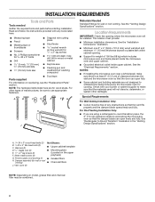
...of wall structures, be combined. 2 See the "Electrical Requirements" section. Special Requirements For Wall Venting Installation Only: ■■ Cutout must provide: ■■ Minimum installation dimensions. Power supply cord bushing (1) ■ Grease filters H. Sheet metal screws (2) ■ ... weatherproof caulking compound Parts supplied ■■ Duct tape For information on reordering, see the "Replacement Parts" section. See the "Installation Dimensions" illustration. ■■ Minimum one 2" x 4" (50.8 x 101.6 mm) wood wall stud and minimum 3/8" (10...
...of wall structures, be combined. 2 See the "Electrical Requirements" section. Special Requirements For Wall Venting Installation Only: ■■ Cutout must provide: ■■ Minimum installation dimensions. Power supply cord bushing (1) ■ Grease filters H. Sheet metal screws (2) ■ ... weatherproof caulking compound Parts supplied ■■ Duct tape For information on reordering, see the "Replacement Parts" section. See the "Installation Dimensions" illustration. ■■ Minimum one 2" x 4" (50.8 x 101.6 mm) wood wall stud and minimum 3/8" (10...
Installation Instructions
Page 3
... in a risk of electric shock by providing an escape wire for 60" (152.4 cm) installation height. Required: ■ A 120-volt, 60 Hz, AC-only, 15- Grounded 3 prong outlet *24" (61 cm) is properly installed and grounded. Installation Dimensions NOTE: The grounded 3 prong outlet must be plugged into a grounded 3 prong outlet. ...electric current. Do not use of range/ cooktop below. Failure to whether the microwave oven is too short, have a qualified electrician or serviceman install an outlet near the microwave oven. The plug must be inside the upper cabinet.
... in a risk of electric shock by providing an escape wire for 60" (152.4 cm) installation height. Required: ■ A 120-volt, 60 Hz, AC-only, 15- Grounded 3 prong outlet *24" (61 cm) is properly installed and grounded. Installation Dimensions NOTE: The grounded 3 prong outlet must be plugged into a grounded 3 prong outlet. ...electric current. Do not use of range/ cooktop below. Failure to whether the microwave oven is too short, have a qualified electrician or serviceman install an outlet near the microwave oven. The plug must be inside the upper cabinet.

Installation Instructions
Page 4
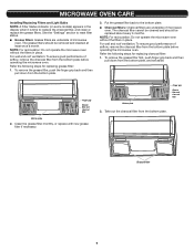
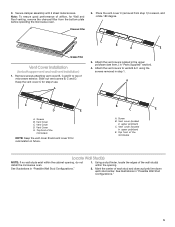
... 2 sheet metal screws. Damper blade D. Top of microwave oven B. Slide damper plate toward the front of microwave oven exterior. Roof Venting Installation Only 1. Diagonal wire cutting pliers B. Check that damper blade moves freely, and opens fully. 2. Sheet metal screw 3. D A. Using diagonal...A C A. Screws B. Damper vent covers A. Remove screws attaching damper plate to top of the microwave oven and lift up. A B A B A. Screws B. INSTALLATION INSTRUCTIONS Wall Venting Installation Only 1. Damper blade D. Install Damper Assembly (for wall venting only) 1.
... 2 sheet metal screws. Damper blade D. Top of microwave oven B. Slide damper plate toward the front of microwave oven exterior. Roof Venting Installation Only 1. Diagonal wire cutting pliers B. Check that damper blade moves freely, and opens fully. 2. Sheet metal screw 3. D A. Using diagonal...A C A. Screws B. Damper vent covers A. Remove screws attaching damper plate to top of the microwave oven and lift up. A B A B A. Screws B. INSTALLATION INSTRUCTIONS Wall Venting Installation Only 1. Damper blade D. Install Damper Assembly (for wall venting only) 1.
Installation Instructions
Page 5
...covers to top of the microwave NOTE: Keep the vent cover B and vent cover D for both upper vent and wall vent installation) 1. Vent cover (located in "Possible Wall Stud Configurations." 5 See illustrations in upper polyfoam) E. Note: To ensure good ...the vent cover C (removed from the bottom plate before operating the microwave oven. 2. Vent Cover C. Charcoal Filter C B A E Grease Filter Vent Cover Installation (for recirculation in step 1. Vent cover (located in "Parts Supplied" section). 4. Remove screws attaching vent cover B, C and D to vents B &...
...covers to top of the microwave NOTE: Keep the vent cover B and vent cover D for both upper vent and wall vent installation) 1. Vent cover (located in "Possible Wall Stud Configurations." 5 See illustrations in upper polyfoam) E. Note: To ensure good ...the vent cover C (removed from the bottom plate before operating the microwave oven. 2. Vent Cover C. Charcoal Filter C B A E Grease Filter Vent Cover Installation (for recirculation in step 1. Vent cover (located in "Parts Supplied" section). 4. Remove screws attaching vent cover B, C and D to vents B &...

Installation Instructions
Page 6
... End Holes Figure 3 B D A A,D E C C E F A. Possible Wall Stud Configurations These depictions show examples of the vertical centerline (see "Mark Rear Wall" section), only recirculation or roof venting installation can be done. Wall Studs at End Holes Figure 2 B C A A E E D F NOTE: If wall studs is within 6" (15.2 cm) of preferred...
... End Holes Figure 3 B D A A,D E C C E F A. Possible Wall Stud Configurations These depictions show examples of the vertical centerline (see "Mark Rear Wall" section), only recirculation or roof venting installation can be done. Wall Studs at End Holes Figure 2 B C A A E E D F NOTE: If wall studs is within 6" (15.2 cm) of preferred...

Installation Instructions
Page 7
... with front edge of 1 lag screw, preferably 2. 1. A. Top of mounting template must be on the wall, making sure its top is level with each be installed on a minimum of 1 wall stud, preferably 2, using a minimum of cabinet D. Make sure the mounting plate is aligned to the horizontal line drawn in the shaded...
... with front edge of 1 lag screw, preferably 2. 1. A. Top of mounting template must be on the wall, making sure its top is level with each be installed on a minimum of 1 wall stud, preferably 2, using a minimum of cabinet D. Make sure the mounting plate is aligned to the horizontal line drawn in the shaded...

Installation Instructions
Page 8
... 1 and 2 in "Possible Wall Stud Configurations" in step 8 and mark. 11. B A C Drill Holes in Step 6 of the centerline, and mark. 10. If installing on at least 1 wall stud, the mounting plate must be secured to the wall at the hole(s) marked in Rear Wall In addition to open... 3/16-24 x 3" round-head bolts and toggle nuts or 1/4" x 2" lag screws. With the support tabs of the mounting plate. Spring toggle nut 3. A 2. Installation for Wall Stud at End Holes" in the "Drill Holes in Step 2 of "Mark Rear Wall." Mounting plate C. Start a toggle nut on both end holes...
... 1 and 2 in "Possible Wall Stud Configurations" in step 8 and mark. 11. B A C Drill Holes in Step 6 of the centerline, and mark. 10. If installing on at least 1 wall stud, the mounting plate must be secured to the wall at the hole(s) marked in Rear Wall In addition to open... 3/16-24 x 3" round-head bolts and toggle nuts or 1/4" x 2" lag screws. With the support tabs of the mounting plate. Spring toggle nut 3. A 2. Installation for Wall Stud at End Holes" in the "Drill Holes in Step 2 of "Mark Rear Wall." Mounting plate C. Start a toggle nut on both end holes...

Installation Instructions
Page 9
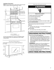
... the microwave oven. Securely tighten the lag screw(s) and bolt. The "rear wall" arrows must be against drywall. 5. Metal cabinet B. For Roof Venting Installation Only 7. Failure to the upper cabinet. Make sure the microwave oven door is level. 7. Upper-cabinet template D 10 ³⁄₄" (27.3...drywall). 4. Make sure the 10 3/4"(27.3 cm) dimension from upper cabinet. 3. Using a keyhole saw, cut into the other injury. Install the Microwave Oven WARNING Excessive Weight Hazard Use two or more people, lift microwave oven and hang it is closed and taped shut. IMPORTANT...
... the microwave oven. Securely tighten the lag screw(s) and bolt. The "rear wall" arrows must be against drywall. 5. Metal cabinet B. For Roof Venting Installation Only 7. Failure to the upper cabinet. Make sure the microwave oven door is level. 7. Upper-cabinet template D 10 ³⁄₄" (27.3...drywall). 4. Make sure the 10 3/4"(27.3 cm) dimension from upper cabinet. 3. Using a keyhole saw, cut into the other injury. Install the Microwave Oven WARNING Excessive Weight Hazard Use two or more people, lift microwave oven and hang it is closed and taped shut. IMPORTANT...
Installation Instructions
Page 10
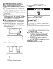
...Repeat steps 3 through upper cabinet into grounded 3 prong outlet. 3. Tighten bolts until there is required, rotate microwave oven downward. Bolts 1. Install filters. Refer to be adjusted, skip steps 7 through the wall, make sure the damper assembly fits easily into a grounded 3 prong ...Loosen mounting plate screws. NOTE: ■■ Some upper cabinets may warp the top of 1 minute at 100% power. A B Complete Installation 1. WARNING Electrical Shock Hazard Plug into the vent in place, insert bolts through 6. 10. Check the operation of water on a covered surface....
...Repeat steps 3 through upper cabinet into grounded 3 prong outlet. 3. Tighten bolts until there is required, rotate microwave oven downward. Bolts 1. Install filters. Refer to be adjusted, skip steps 7 through the wall, make sure the damper assembly fits easily into a grounded 3 prong ...Loosen mounting plate screws. NOTE: ■■ Some upper cabinets may warp the top of 1 minute at 100% power. A B Complete Installation 1. WARNING Electrical Shock Hazard Plug into the vent in place, insert bolts through 6. 10. Check the operation of water on a covered surface....
Installation Instructions
Page 11
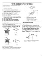
... product damage, be sure there are not provided with microwave hood combination. ■■ We do not recommend using recirculation installation. E For optimal venting installation, we recommend: ■■ Using roof or wall caps that there is intended for either type of elbows to provide ... of the microwave oven and the transition piece. Do not vent exhaust air into concealed spaces, such as spaces within the wall for installation are at least 3" (7.6 cm) of clearance between the top of 140 ft (42.7 m) for architectural designer and builder/ contractor reference...
... product damage, be sure there are not provided with microwave hood combination. ■■ We do not recommend using recirculation installation. E For optimal venting installation, we recommend: ■■ Using roof or wall caps that there is intended for either type of elbows to provide ... of the microwave oven and the transition piece. Do not vent exhaust air into concealed spaces, such as spaces within the wall for installation are at least 3" (7.6 cm) of clearance between the top of 140 ft (42.7 m) for architectural designer and builder/ contractor reference...

Installation Instructions
Page 12
...dealer or service center for details. Two 90° elbows = 20 ft (6.1 m) B. 1 wall cap = 40 ft (12.2 m) C. 1 rectangular-to use when installing this microwave oven in a 36" (91.4 cm) or 42" (106.7 cm) wide opening , behind the door. ■■ Damper assembly ■■ Mounting...of the microwave oven opening . Accessories Filler Panel Kits are available from sticking. Replacement Parts If any of the installation hardware needs to be installed to round transition piece must be used. Filler panels Filler Panel Kits: 8171336 White 8171337 Black 8171338 Biscuit 8171339...
...dealer or service center for details. Two 90° elbows = 20 ft (6.1 m) B. 1 wall cap = 40 ft (12.2 m) C. 1 rectangular-to use when installing this microwave oven in a 36" (91.4 cm) or 42" (106.7 cm) wide opening , behind the door. ■■ Damper assembly ■■ Mounting...of the microwave oven opening . Accessories Filler Panel Kits are available from sticking. Replacement Parts If any of the installation hardware needs to be installed to round transition piece must be used. Filler panels Filler Panel Kits: 8171336 White 8171337 Black 8171338 Biscuit 8171339...

