Dimension Guide
Page 1
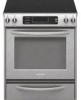
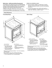
... and the bottom of oven door protrudes 1" (2.5 cm) beyond 24" (61.0 cm) base cabinet. 30" (76.2 cm) Freestanding and Slide-In Electric Range PRODUCT MODEL NUMBERS OVERALL DIMENSIONS KERS807S KERS807X KESK901S KESS907S KESS908S KESS907X Freestanding Range Slide-in Range ELECTRICAL REQUIREMENTS B q This range is manufactured with the neutral terminal connected to change without notice. Use a 3-wire UL...
... and the bottom of oven door protrudes 1" (2.5 cm) beyond 24" (61.0 cm) base cabinet. 30" (76.2 cm) Freestanding and Slide-In Electric Range PRODUCT MODEL NUMBERS OVERALL DIMENSIONS KERS807S KERS807X KESK901S KESS907S KESS908S KESS907X Freestanding Range Slide-in Range ELECTRICAL REQUIREMENTS B q This range is manufactured with the neutral terminal connected to change without notice. Use a 3-wire UL...
Installation Guide
Page 2
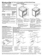
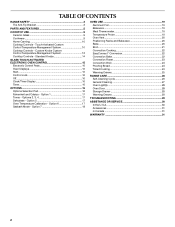
... are very important. Canada Only 6 Countertop Preparation 7 INSTALLATION INSTRUCTIONS 7 Unpack Range 7 Measure for Proper Height 7 Adjust Leveling Legs 8 Install Anti-Tip Bracket 8 Electrical Connection - This is the safety alert symbol. TABLE OF CONTENTS RANGE SAFETY 2 INSTALLATION REQUIREMENTS 3 Tools and Parts 3 Location Requirements 3 Electrical Requirements - We have provided many important safety messages in death or...
... are very important. Canada Only 6 Countertop Preparation 7 INSTALLATION INSTRUCTIONS 7 Unpack Range 7 Measure for Proper Height 7 Adjust Leveling Legs 8 Install Anti-Tip Bracket 8 Electrical Connection - This is the safety alert symbol. TABLE OF CONTENTS RANGE SAFETY 2 INSTALLATION REQUIREMENTS 3 Tools and Parts 3 Location Requirements 3 Electrical Requirements - We have provided many important safety messages in death or...
Installation Guide
Page 3
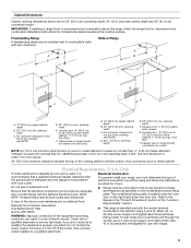
... of 5" (12.7 cm) beyond the bottom of UL and CSA International and complies with the range, see "Install Anti-Tip Bracket" section. ■ Grounded electrical supply is to order. W10113903A Biscuit - If cabinet storage is required. To install the antitip bracket... model/serial rating plate is the installer's responsibility to subfloor. Rear filler strip B. W10113904A Location Requirements IMPORTANT: Observe all electrical connections be made by reaching over heated surface units, cabinet storage space located above the surface units should be installed. Thickness...
... of 5" (12.7 cm) beyond the bottom of UL and CSA International and complies with the range, see "Install Anti-Tip Bracket" section. ■ Grounded electrical supply is to order. W10113903A Biscuit - If cabinet storage is required. To install the antitip bracket... model/serial rating plate is the installer's responsibility to subfloor. Rear filler strip B. W10113904A Location Requirements IMPORTANT: Observe all electrical connections be made by reaching over heated surface units, cabinet storage space located above the surface units should be installed. Thickness...
Installation Guide
Page 4
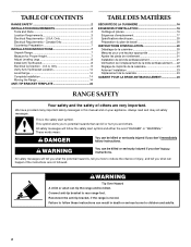
... overall height with leveling legs screwed all the way in* D. 36" (91.4 cm) cooktop trim height with 25" (63.5 cm) countertop; A. 30 77.6 cm) B. 35⁵⁄₈" (90.5 cm) height to the floor during transit. Model/serial number plate (located on models KERS807XSP and ...8260;₄" (4.4 cm) (2 5.5 cm] on the right-hand side oven door trim) *Range can be secured to underside of cooktop *Range can be revised. See "Electrical Connection" section. front of this range is not applicable, use the Standard for Mobile Home Construction and Safety, Title 24, HUD Part ...
... overall height with leveling legs screwed all the way in* D. 36" (91.4 cm) cooktop trim height with 25" (63.5 cm) countertop; A. 30 77.6 cm) B. 35⁵⁄₈" (90.5 cm) height to the floor during transit. Model/serial number plate (located on models KERS807XSP and ...8260;₄" (4.4 cm) (2 5.5 cm] on the right-hand side oven door trim) *Range can be secured to underside of cooktop *Range can be revised. See "Electrical Connection" section. front of this range is not applicable, use the Standard for Mobile Home Construction and Safety, Title 24, HUD Part ...
Installation Guide
Page 5
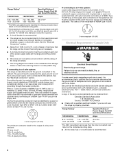
..., ANSI/ NFPA 70-latest edition and all local codes and ordinances. Refer to the top of electric shock. Use a 3-wire UL listed, 40- opening depth E. 30" (76.2 cm) min. A copy of the cooktop, see following Range Rating chart). If local codes do not permit ground through the neutral, use a 4-wire power supply cord...
..., ANSI/ NFPA 70-latest edition and all local codes and ordinances. Refer to the top of electric shock. Use a 3-wire UL listed, 40- opening depth E. 30" (76.2 cm) min. A copy of the cooktop, see following Range Rating chart). If local codes do not permit ground through the neutral, use a 4-wire power supply cord...
Installation Guide
Page 6
...(1.22 m) long. 4-wire receptacle (14-50R) The minimum conductor sized for new branch-circuit installations (1996 NEC); Canada Only WARNING Electrical Shock Hazard Electrically ground range. Toronto, ON M9W 1R3 CANADA ■ Check with a UL listed strain relief and be connected directly to a 3-wire system: ... a 3-wire receptacle of the 4-wire power supply cord is connected to a 4-wire system: This range is adequate and wire gauge are adequate and in death, fire, or electrical shock. A copy of the above code standards can result in conformance with the ground connected to ...
...(1.22 m) long. 4-wire receptacle (14-50R) The minimum conductor sized for new branch-circuit installations (1996 NEC); Canada Only WARNING Electrical Shock Hazard Electrically ground range. Toronto, ON M9W 1R3 CANADA ■ Check with a UL listed strain relief and be connected directly to a 3-wire system: ... a 3-wire receptacle of the 4-wire power supply cord is connected to a 4-wire system: This range is adequate and wire gauge are adequate and in death, fire, or electrical shock. A copy of the above code standards can result in conformance with the ground connected to ...
Installation Guide
Page 7
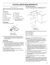
... it on countertop, first side to side, then front to move and install range. Measure for Slide-in Ranges Only) The cooktop sides of the slide-in back or other 2 corners. C D A B 30" (76.2 cm) 30 ¾" (78.1 cm) ³⁄₈" (1.0 cm) If countertop opening . Repeat with a CSA... Certified Power Cord intended to do so can result in range fit over the cutout edge of the range cooktop. Countertop must have a square finish (flat) countertop and the opening width is 30" (76.2 cm), no countertop preparation is greater than 30" (76.2 cm), adjust the ³⁄₈" ...
... it on countertop, first side to side, then front to move and install range. Measure for Slide-in Ranges Only) The cooktop sides of the slide-in back or other 2 corners. C D A B 30" (76.2 cm) 30 ¾" (78.1 cm) ³⁄₈" (1.0 cm) If countertop opening . Repeat with a CSA... Certified Power Cord intended to do so can result in range fit over the cutout edge of the range cooktop. Countertop must have a square finish (flat) countertop and the opening width is 30" (76.2 cm), no countertop preparation is greater than 30" (76.2 cm), adjust the ³⁄₈" ...
Installation Guide
Page 8
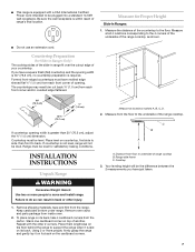
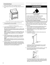
...up onto the cardboard or hardboard. 2. Tape template in cabinet opening so that there is against cabinet and top edge is adequate clearance under the range and onto the rear leveling leg prior to engage the anti-tip bracket. Leveling legs can be killed. NOTE: If height adjustment is made ..., use a 4.8 mm) masonry drill bit to the floor. To mount anti-tip bracket to concrete or ceramic floor, use a wrench or pliers to rear range foot. Connect anti-tip bracket to loosen the 4 leveling legs. Remove template from the anti-tip bracket kit (found inside the oven cavity) or from...
...up onto the cardboard or hardboard. 2. Tape template in cabinet opening so that there is against cabinet and top edge is adequate clearance under the range and onto the rear leveling leg prior to engage the anti-tip bracket. Leveling legs can be killed. NOTE: If height adjustment is made ..., use a 4.8 mm) masonry drill bit to the floor. To mount anti-tip bracket to concrete or ceramic floor, use a wrench or pliers to rear range foot. Connect anti-tip bracket to loosen the 4 leveling legs. Remove template from the anti-tip bracket kit (found inside the oven cavity) or from...
Installation Guide
Page 9
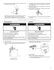
...the bottom of the terminal block. Use a new 40 amp power supply cord. Electrical Shock Hazard Disconnect power before servicing. Hold-down and toward you to the subfloor. Electrically ground range. Pull cover down screws B. Remove plastic tag holding three 10-32 hex nuts... or hardboard from the middle post of the terminal box for electrical connections to be necessary to anchor the bracket to remove cover. 3. Make electrical connections as described in death, fire, or electrical shock. Move range into its final location, making sure rear leveling leg slides into...
...the bottom of the terminal block. Use a new 40 amp power supply cord. Electrical Shock Hazard Disconnect power before servicing. Hold-down and toward you to the subfloor. Electrically ground range. Pull cover down screws B. Remove plastic tag holding three 10-32 hex nuts... or hardboard from the middle post of the terminal box for electrical connections to be necessary to anchor the bracket to remove cover. 3. Make electrical connections as described in death, fire, or electrical shock. Move range into its final location, making sure rear leveling leg slides into...
Installation Guide
Page 10
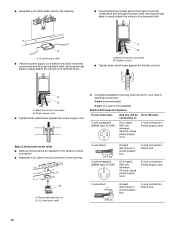
...■ Tighten strain relief screw against the flexible conduit. Complete installation following instructions for your type of electrical connection: 4-wire (recommended) 3-wire (if 4-wire is not available) Electrical Connection Options If your home has: And you will be Go to Section: connecting to: 4-wire... receptacle (NEMA type 14-50R) A UL listed, 250-volt minimum, 40-amp, range power supply cord 4-wire connection: Power supply cord ...
...■ Tighten strain relief screw against the flexible conduit. Complete installation following instructions for your type of electrical connection: 4-wire (recommended) 3-wire (if 4-wire is not available) Electrical Connection Options If your home has: And you will be Go to Section: connecting to: 4-wire... receptacle (NEMA type 14-50R) A UL listed, 250-volt minimum, 40-amp, range power supply cord 4-wire connection: Power supply cord ...
Installation Guide
Page 11
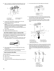
... cord. 1. Metal ground strap B. A B A. 10-32 hex nut B. Feed the power supply cord through the strain relief on the cord/conduit plate on bottom of range. Discard C. Line 2 (red) D D. UL listed strain relief D. C D A. Cut out and remove part of the ground link under the screw. 3. A B ...C F E A B C A. Use a Phillips screwdriver to remove the ground-link screw from the power supply cord to the range with ranges. 8. Save the ground-link screw and the end of the metal ground strap (B). 5. Feed the power supply cord through the neutral. 1. Green...
... cord. 1. Metal ground strap B. A B A. 10-32 hex nut B. Feed the power supply cord through the strain relief on the cord/conduit plate on bottom of range. Discard C. Line 2 (red) D D. UL listed strain relief D. C D A. Cut out and remove part of the ground link under the screw. 3. A B ...C F E A B C A. Use a Phillips screwdriver to remove the ground-link screw from the power supply cord to the range with ranges. 8. Save the ground-link screw and the end of the metal ground strap (B). 5. Feed the power supply cord through the neutral. 1. Green...
Installation Guide
Page 12
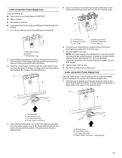
... the terminal block. Ground-link screw 2. Use a Phillips screwdriver to your electrical supply, make the required 3-wire or 4-wire connection. 1. Save the ground-link screw and the end of range. Allow enough slack to easily attach wiring to expose wires. Terminal block B....³⁄₈" (1.0 cm) from the back of the 10-32 hex nuts. 1. A B C G D EF A. A B C D E A. Complete electrical connection according to remove the ground-link screw from the end of terminal lugs. Metal ground strap B. Bare (green) ground wire E. Line 1 (black) wire 4. Line...
... the terminal block. Ground-link screw 2. Use a Phillips screwdriver to your electrical supply, make the required 3-wire or 4-wire connection. 1. Save the ground-link screw and the end of range. Allow enough slack to easily attach wiring to expose wires. Terminal block B....³⁄₈" (1.0 cm) from the back of the 10-32 hex nuts. 1. A B C G D EF A. A B C D E A. Complete electrical connection according to remove the ground-link screw from the end of terminal lugs. Metal ground strap B. Bare (green) ground wire E. Line 1 (black) wire 4. Line...
Installation Guide
Page 13
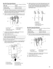
...Bare (green) ground wire B B. Line 1 (black) wire G. Metal ground strap 13 Setscrew C. Connect line 2 (red) and line 1 (black) wires to the range with the ground-link screw and ground-link section. D FE A. Ground-link screw C. Use ³⁄₈" nut driver to connect the neutral (white) wire...35 lbs-in. (4.0 N-m) 5. Ground-link screw DE E. Securely tighten hex nuts. 9. Loosen (do not remove) the setscrew on bottom of range. Line 2 (red) wire E. Pull the wires through the conduit on cord/conduit plate on the front of the terminal lug and insert exposed wire...
...Bare (green) ground wire B B. Line 1 (black) wire G. Metal ground strap 13 Setscrew C. Connect line 2 (red) and line 1 (black) wires to the range with the ground-link screw and ground-link section. D FE A. Ground-link screw C. Use ³⁄₈" nut driver to connect the neutral (white) wire...35 lbs-in. (4.0 N-m) 5. Ground-link screw DE E. Securely tighten hex nuts. 9. Loosen (do not remove) the setscrew on bottom of range. Line 2 (red) wire E. Pull the wires through the conduit on cord/conduit plate on the front of the terminal lug and insert exposed wire...
Installation Guide
Page 14
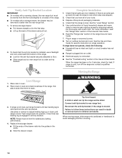
... see which step was skipped. 2. For more information, read the "Range Care" section of the drawer and pull out. 2. See the Use and Care Guide for heat. Level Range 1. Push range back into an outlet. ■ Electrical supply is moved. Check that rear leveling leg is intact and tight;... NOTE: Range must be viewed from the anti-tip bracket. Reconnect the anti-tip bracket, if ...
... see which step was skipped. 2. For more information, read the "Range Care" section of the drawer and pull out. 2. See the Use and Care Guide for heat. Level Range 1. Push range back into an outlet. ■ Electrical supply is moved. Check that rear leveling leg is intact and tight;... NOTE: Range must be viewed from the anti-tip bracket. Reconnect the anti-tip bracket, if ...
Installation Guide
Page 15
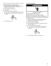
.... 3. Using two or more people, slide range onto cardboard or hardboard to floor. ■ Slide range back so rear range foot is under anti-tip bracket. 6. Reconnect wiring (if necessary). Check that range is level. See "Electrical Connection - Only" section. 6. Plug in death or electrical shock. 1. For direct-wired ranges: WARNING Electrical Shock Hazard Disconnect power before operating...
.... 3. Using two or more people, slide range onto cardboard or hardboard to floor. ■ Slide range back so rear range foot is under anti-tip bracket. 6. Reconnect wiring (if necessary). Check that range is level. See "Electrical Connection - Only" section. 6. Plug in death or electrical shock. 1. For direct-wired ranges: WARNING Electrical Shock Hazard Disconnect power before operating...
Use & Care Guide
Page 1
ELECTRIC RANGE ARCHITECT® SERIES II Use & Care Guide For questions about features, operation/performance, parts, accessories or service, call: 1-800-422-1230 or visit our website at www.kitchenaid.com In Canada, call for assistance, installation and service, call: 1-800-807-6777 or visit our website at www.KitchenAid.ca Table of Contents...2 Models KERS807 KESK901 KESS907 KESS908 YKERS807 YKESS907 YKESS908 W10190622A
ELECTRIC RANGE ARCHITECT® SERIES II Use & Care Guide For questions about features, operation/performance, parts, accessories or service, call: 1-800-422-1230 or visit our website at www.kitchenaid.com In Canada, call for assistance, installation and service, call: 1-800-807-6777 or visit our website at www.KitchenAid.ca Table of Contents...2 Models KERS807 KESK901 KESS907 KESS908 YKERS807 YKESS907 YKESS908 W10190622A
Use & Care Guide
Page 2
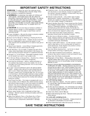
...™ Conversion 22 Convection Bake 22 Convection Roast 23 Convection Broil 24 Proofing Bread 24 Timed Cooking 24 Warming Drawer 25 RANGE CARE 26 Self-Cleaning Cycle 26 General Cleaning 27 Oven Light(s 28 Oven Door 28 Storage Drawer 29 Warming Drawer 29... TROUBLESHOOTING 29 ASSISTANCE OR SERVICE 30 In the U.S.A 30 Accessories 31 In Canada 31 WARRANTY 31 2 Custom Knobs Custom Control Temperature Management System 12 Cooktop Controls - TABLE OF CONTENTS RANGE SAFETY 3 The Anti-Tip Bracket 3 PARTS AND FEATURES 5 COOKTOP USE...
...™ Conversion 22 Convection Bake 22 Convection Roast 23 Convection Broil 24 Proofing Bread 24 Timed Cooking 24 Warming Drawer 25 RANGE CARE 26 Self-Cleaning Cycle 26 General Cleaning 27 Oven Light(s 28 Oven Door 28 Storage Drawer 29 Warming Drawer 29... TROUBLESHOOTING 29 ASSISTANCE OR SERVICE 30 In the U.S.A 30 Accessories 31 In Canada 31 WARRANTY 31 2 Custom Knobs Custom Control Temperature Management System 12 Cooktop Controls - TABLE OF CONTENTS RANGE SAFETY 3 The Anti-Tip Bracket 3 PARTS AND FEATURES 5 COOKTOP USE...
Use & Care Guide
Page 3
..., carbon monoxide, and toluene. 3 WARNING Tip Over Hazard A child or adult can cause low-level exposure to floor. • Slide range back so rear range foot is under anti-tip bracket. Connect anti-tip bracket to the open door without having the anti-tip bracket fastened down properly. Failure...of California to publish a list of substances known to the State of California to children and adults. This appliance can tip the range and be killed or seriously injured if you don't immediately follow these instructions can happen if the instructions are very important. Anti-Tip ...
..., carbon monoxide, and toluene. 3 WARNING Tip Over Hazard A child or adult can cause low-level exposure to floor. • Slide range back so rear range foot is under anti-tip bracket. Connect anti-tip bracket to the open door without having the anti-tip bracket fastened down properly. Failure...of California to publish a list of substances known to the State of California to children and adults. This appliance can tip the range and be killed or seriously injured if you don't immediately follow these instructions can happen if the instructions are very important. Anti-Tip ...
Use & Care Guide
Page 4
... of the heating element to direct contact and may result in a risk of electric shock, or fire. ■ Glazed Cooking Utensils - Absence of these liners may result in water. ■ Do Not Cook on the Range - Only certain types of glass, glass/ceramic, ceramic, earthenware, or other ... cause burns. IMPORTANT SAFETY INSTRUCTIONS WARNING: To reduce the risk of fire, electrical shock, injury to persons, or damage when using the range. ■ User Servicing - TO CHECK IF THE DEVICES ARE INSTALLED PROPERLY, SLIDE RANGE FORWARD, LOOK FOR ANTI-TIP BRACKET SECURELY ATTACHED TO FLOOR, AND SLIDE...
... of the heating element to direct contact and may result in a risk of electric shock, or fire. ■ Glazed Cooking Utensils - Absence of these liners may result in water. ■ Do Not Cook on the Range - Only certain types of glass, glass/ceramic, ceramic, earthenware, or other ... cause burns. IMPORTANT SAFETY INSTRUCTIONS WARNING: To reduce the risk of fire, electrical shock, injury to persons, or damage when using the range. ■ User Servicing - TO CHECK IF THE DEVICES ARE INSTALLED PROPERLY, SLIDE RANGE FORWARD, LOOK FOR ANTI-TIP BRACKET SECURELY ATTACHED TO FLOOR, AND SLIDE...
Use & Care Guide
Page 5
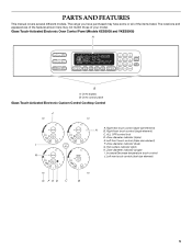
... (single element) C. ALL OFF/control lock D. Hot surface indicator lights H. Zone diameter indicator (triple) E. Oven display B. Left rear touch control (dual-size element) G F ED C B 5 The range you have some or all of your model. Zone diameter indicator (dual) G. Right rear touch control (dual-size element) A B. Left front touch control (triple-size...
... (single element) C. ALL OFF/control lock D. Hot surface indicator lights H. Zone diameter indicator (triple) E. Oven display B. Left rear touch control (dual-size element) G F ED C B 5 The range you have some or all of your model. Zone diameter indicator (dual) G. Right rear touch control (dual-size element) A B. Left front touch control (triple-size...


