Installation Instructions
Page 1
IMPORTANT: Installer: Leave Installation Instructions with the homeowner. Save Installation Instructions for future reference. Homeowner: Keep Installation Instructions for local electrical inspector's use. Write down the model and serial numbers before installing cooktop. Both numbers are on the model/serial rating plate, located on the bottom of the cooktop. Model Serial Part No. 8286553 Installation Instructions 30" (76.2 cm) and 36" (91.4 cm) ELECTRIC Built-in Ceramic Downdraft Cooktop IMPORTANT: Read and save these instructions.
IMPORTANT: Installer: Leave Installation Instructions with the homeowner. Save Installation Instructions for future reference. Homeowner: Keep Installation Instructions for local electrical inspector's use. Write down the model and serial numbers before installing cooktop. Both numbers are on the model/serial rating plate, located on the bottom of the cooktop. Model Serial Part No. 8286553 Installation Instructions 30" (76.2 cm) and 36" (91.4 cm) ELECTRIC Built-in Ceramic Downdraft Cooktop IMPORTANT: Read and save these instructions.
Installation Instructions
Page 2
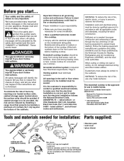
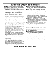
WARNING You can be reduced by reaching over heated surface units, cabinet storage space located above the surface units should be done by qualified person(s) in kitchen. If cabinet storage is your responsibility. • Make sure you... 8501 East Pleasant Valley Road Cleveland, Ohio 44131-5575 Tools and materials needed for installation: Parts supplied: Phillips screwdriver metal snips safety glasses pliers • literature pack • vent cover • glass cleaner caulking gun with weatherproof caulking tape measure 2 hand or electric drill duct tape gloves ...
WARNING You can be reduced by reaching over heated surface units, cabinet storage space located above the surface units should be done by qualified person(s) in kitchen. If cabinet storage is your responsibility. • Make sure you... 8501 East Pleasant Valley Road Cleveland, Ohio 44131-5575 Tools and materials needed for installation: Parts supplied: Phillips screwdriver metal snips safety glasses pliers • literature pack • vent cover • glass cleaner caulking gun with weatherproof caulking tape measure 2 hand or electric drill duct tape gloves ...
Installation Instructions
Page 6
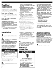
... Turn power supply off before inserting cooktop into cutout. Failure to move and install cooktop. latest edition*, or CSA Standards C22.1-94, Canadian Electrical Code, Part 1 and 22.2 No. 0-M91 - This cooktop is No.-10 gauge. Connect the cooktop cable to local codes and ordinances. 5. Do Not have a fuse in countertop...
... Turn power supply off before inserting cooktop into cutout. Failure to move and install cooktop. latest edition*, or CSA Standards C22.1-94, Canadian Electrical Code, Part 1 and 22.2 No. 0-M91 - This cooktop is No.-10 gauge. Connect the cooktop cable to local codes and ordinances. 5. Do Not have a fuse in countertop...
Installation Instructions
Page 8
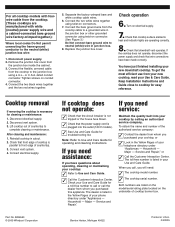
... Refer to Use and Care Guide. ✓ Call the Customer Interaction Center. Tighten screws on electrical supply. 7. Check that cooktop surface elements heat and indicator lights are listed on the model/serial rating plate located on connectors. 7. Disconnect vent system. 3. Check that... 8. Disconnect power supply. 2. or C.S.A.-listed conduit connector. Note: Refer to Use and Care Guide for easy reference. Service and Repair." Part No. 8286553 © 2005 Whirlpool Corporation Benton Harbor, Michigan 49022 Printed in cutout. 2. Turn on conduit connector. 4. You have been ...
... Refer to Use and Care Guide. ✓ Call the Customer Interaction Center. Tighten screws on electrical supply. 7. Check that cooktop surface elements heat and indicator lights are listed on the model/serial rating plate located on connectors. 7. Disconnect vent system. 3. Check that... 8. Disconnect power supply. 2. or C.S.A.-listed conduit connector. Note: Refer to Use and Care Guide for easy reference. Service and Repair." Part No. 8286553 © 2005 Whirlpool Corporation Benton Harbor, Michigan 49022 Printed in cutout. 2. Turn on conduit connector. 4. You have been ...
Use and Care Guide
Page 2
TABLE OF CONTENTS COOKTOP SAFETY 2 PARTS AND FEATURES 4 COOKTOP CONTROLS 6 Knob Controls 6 Dual/Triple-Size Elements 6 Downdraft Vent System 7 Home Canning 7 Cookware 7 COOKTOP CARE 8 General Cleaning 8 TROUBLESHOOTING 8 ASSISTANCE OR SERVICE 9 In ...
TABLE OF CONTENTS COOKTOP SAFETY 2 PARTS AND FEATURES 4 COOKTOP CONTROLS 6 Knob Controls 6 Dual/Triple-Size Elements 6 Downdraft Vent System 7 Home Canning 7 Cookware 7 COOKTOP CARE 8 General Cleaning 8 TROUBLESHOOTING 8 ASSISTANCE OR SERVICE 9 In ...
Use and Care Guide
Page 3
...part of the cooktop. Children should not be referred to avoid steam burn. Flammable materials should not be allowed to sit or stand on the cooktop to wipe spills on . Only certain types of glass, glass/ceramic, ceramic, earthenware, or other flammable materials contact surface units or areas near surface... units. s Utensil Handles Should Be Turned Inward and Not Extend Over Adjacent Surface Units - Smother fire or flame or ...
...part of the cooktop. Children should not be referred to avoid steam burn. Flammable materials should not be allowed to sit or stand on the cooktop to wipe spills on . Only certain types of glass, glass/ceramic, ceramic, earthenware, or other flammable materials contact surface units or areas near surface... units. s Utensil Handles Should Be Turned Inward and Not Extend Over Adjacent Surface Units - Smother fire or flame or ...
Use and Care Guide
Page 4
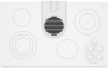
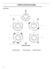
Right front control knob 4 Left front control knob D. Downdraft fan knob B. Left rear control knob C. Control Panel A B E C F D A. Power on indicator light E. Right rear control knob F. The cooktop you have purchased may have some or all of the items listed. PARTS AND FEATURES This manual covers different models.
Right front control knob 4 Left front control knob D. Downdraft fan knob B. Left rear control knob C. Control Panel A B E C F D A. Power on indicator light E. Right rear control knob F. The cooktop you have purchased may have some or all of the items listed. PARTS AND FEATURES This manual covers different models.
Use and Care Guide
Page 9
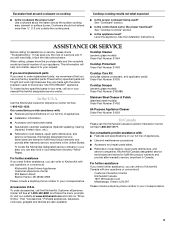
...surface burner. Cookware should not extend more than ¹⁄₂" (1.3 cm) outside the cooking area. See "Cookware" section. If you still need help us to better respond to fulfill the product warranty and provide after -warranty service, anywhere in your area, call the KitchenAid... Yellow Pages. Cooktop Cleaner (ceramic glass models) Order Part Number 31464 Cooktop Protectant Order Part Number 31463 If you need to build every new KITCHENAID® appliance. To locate the KitchenAid designated service company in your area, you need replacement parts If you can also look...
...surface burner. Cookware should not extend more than ¹⁄₂" (1.3 cm) outside the cooking area. See "Cookware" section. If you still need help us to better respond to fulfill the product warranty and provide after -warranty service, anywhere in your area, call the KitchenAid... Yellow Pages. Cooktop Cleaner (ceramic glass models) Order Part Number 31464 Cooktop Protectant Order Part Number 31463 If you need to build every new KITCHENAID® appliance. To locate the KitchenAid designated service company in your area, you need replacement parts If you can also look...
Use and Care Guide
Page 10
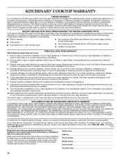
... or workmanship: ■ Electric element ■ Gas burners ■ Solid state touch control system parts ■ Any cracking of the rubber seal between the ceramic glass cooktop and porcelain edge ■ Any cracking due to correct the installation of your major appliance. DISCLAIMER... removal from your home of the ceramic glass cooktop ■ Surface unit elements This limited warranty does not cover: ITEMS EXCLUDED FROM WARRANTY 1. You can find additional help by checking the "Assistance or Service" section or by a KitchenAid designated service company. Dealer name Address...
... or workmanship: ■ Electric element ■ Gas burners ■ Solid state touch control system parts ■ Any cracking of the rubber seal between the ceramic glass cooktop and porcelain edge ■ Any cracking due to correct the installation of your major appliance. DISCLAIMER... removal from your home of the ceramic glass cooktop ■ Surface unit elements This limited warranty does not cover: ITEMS EXCLUDED FROM WARRANTY 1. You can find additional help by checking the "Assistance or Service" section or by a KitchenAid designated service company. Dealer name Address...
Parts List
Page 1
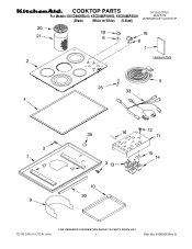
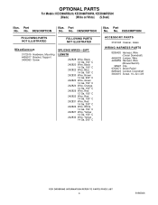
COOKTOP PARTS 36" ELECTRIC For Models: KECD866RBL00, KECD866RWW00, KECD866RSS00 BUILT−IN DOWNDRDAFT COOKTOP (Black) (White on White) (S.Steel) 12−05 Litho in U.S.A. (cre) 1 Part No. 8186306 Rev.A
COOKTOP PARTS 36" ELECTRIC For Models: KECD866RBL00, KECD866RWW00, KECD866RSS00 BUILT−IN DOWNDRDAFT COOKTOP (Black) (White on White) (S.Steel) 12−05 Litho in U.S.A. (cre) 1 Part No. 8186306 Rev.A

Parts List
Page 2
... 30 3193032 Gasket, Vent Shield 33 8286055 Light, Hot Surface Indicator 35 3193094 Plate, Cover 2 8186306 No. Part No. No. DESCRIPTION 1 Literature Parts 7 8285810 Box, Burner 8286553 Installation 8 3183956 Seal, ...Switch Cover Instructions 9 8285934 Shield, Vent 8286428 Wiring Diagram 3177991 Screw 8286080 Use & Care Guide 10 3190656 Drip Bowl, Grease 3191638 Safe Cooking Tips 11 4455354 Bracket, Mounting 9759133 Safe Cooking Tips Control 2 Cooktop, Glass...
... 30 3193032 Gasket, Vent Shield 33 8286055 Light, Hot Surface Indicator 35 3193094 Plate, Cover 2 8186306 No. Part No. No. DESCRIPTION 1 Literature Parts 7 8285810 Box, Burner 8286553 Installation 8 3183956 Seal, ...Switch Cover Instructions 9 8285934 Shield, Vent 8286428 Wiring Diagram 3177991 Screw 8286080 Use & Care Guide 10 3190656 Drip Bowl, Grease 3191638 Safe Cooking Tips 11 4455354 Bracket, Mounting 9759133 Safe Cooking Tips Control 2 Cooktop, Glass...
Parts List
Page 3
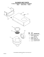
Part No. DESCRIPTION 1 8285958 Bracket, Shield 2 3192403 Bracket, Blower Mounting 4 9760484 Ring, Inlet 5 9760485 Screen, Inlet 6 9760483 Adapter, Vent 7 9760440 Blower Motor Asm. (Includes Fan Asm) 8 3196537 Screw, 8−18 x 3/8 3 BLOWER UNIT PARTS For Models: KECD866RBL00, KECD866RWW00, KECD866RSS00 (Black) (White on White) (S.Steel) 8186306 Illus. No.
Part No. DESCRIPTION 1 8285958 Bracket, Shield 2 3192403 Bracket, Blower Mounting 4 9760484 Ring, Inlet 5 9760485 Screen, Inlet 6 9760483 Adapter, Vent 7 9760440 Blower Motor Asm. (Includes Fan Asm) 8 3196537 Screw, 8−18 x 3/8 3 BLOWER UNIT PARTS For Models: KECD866RBL00, KECD866RWW00, KECD866RSS00 (Black) (White on White) (S.Steel) 8186306 Illus. No.
Parts List
Page 4
... PARTS 3191048 Cleaner, Glass WIRING HARNESS PARTS 8286420 Harness, Wire (Ceran Downdraft) 4456028 Jumper, Wire 4456859 Harness, Wire (Blower/Switch) 98997 Clip 9760671 Strain Relief 8286423 Conduit, Downdraft 3400015 Screw, 10−32 x 3/8 4 8186306 Part No. No. Part No. Part No. No. No. OPTIONAL PARTS ...Yellow 14 Ga. 150 C 242832 Wire, Yellow 14 Ga. 200 C Illus. DESCRIPTION FOLLOWING PARTS NOT ILLUSTRATED FOLLOWING PARTS NOT ILLUSTRATED Miscellaneous 3172515 Hardware, Mounting 4455917 Bracket, Support 3400093 Screw SPLICING WIRES−−25FT. DESCRIPTION Illus.
... PARTS 3191048 Cleaner, Glass WIRING HARNESS PARTS 8286420 Harness, Wire (Ceran Downdraft) 4456028 Jumper, Wire 4456859 Harness, Wire (Blower/Switch) 98997 Clip 9760671 Strain Relief 8286423 Conduit, Downdraft 3400015 Screw, 10−32 x 3/8 4 8186306 Part No. No. Part No. Part No. No. No. OPTIONAL PARTS ...Yellow 14 Ga. 150 C 242832 Wire, Yellow 14 Ga. 200 C Illus. DESCRIPTION FOLLOWING PARTS NOT ILLUSTRATED FOLLOWING PARTS NOT ILLUSTRATED Miscellaneous 3172515 Hardware, Mounting 4455917 Bracket, Support 3400093 Screw SPLICING WIRES−−25FT. DESCRIPTION Illus.


