Installation Instructions
Page 1
Installation Instructions 30" (76.2 cm) and 36" (91.4 cm) ELECTRIC Built-in Ceramic Downdraft Cooktop IMPORTANT: Read and save these instructions. Both numbers are on the model/serial rating plate, located on the bottom of the cooktop. IMPORTANT: Installer: Leave Installation Instructions with the homeowner. Model Serial Part No. 8286553 Homeowner: Keep Installation Instructions for local electrical inspector's use. Write down the model and serial numbers before installing cooktop. Save Installation Instructions for future reference.
Installation Instructions 30" (76.2 cm) and 36" (91.4 cm) ELECTRIC Built-in Ceramic Downdraft Cooktop IMPORTANT: Read and save these instructions. Both numbers are on the model/serial rating plate, located on the bottom of the cooktop. IMPORTANT: Installer: Leave Installation Instructions with the homeowner. Model Serial Part No. 8286553 Homeowner: Keep Installation Instructions for local electrical inspector's use. Write down the model and serial numbers before installing cooktop. Save Installation Instructions for future reference.
Installation Instructions
Page 2
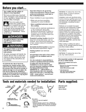
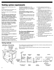
...hurt you have provided many important safety messages in this cooktop. • Comply with the electrical specifications on the bottom of the cabinets. Model/serial rating plate is required. Grounded electrical system is located on the model/serial rating plate. Venting system must be vented to ...and to prevent back drafting. WARNING: To reduce the risk of fire, electric shock, or injury to make sure that projects horizontally a minimum of 5 inches (12.7 cm) beyond the bottom of the cooktop. Ducted fans must be done by reaching over heated surface units, cabinet...
...hurt you have provided many important safety messages in this cooktop. • Comply with the electrical specifications on the bottom of the cabinets. Model/serial rating plate is required. Grounded electrical system is located on the model/serial rating plate. Venting system must be vented to ...and to prevent back drafting. WARNING: To reduce the risk of fire, electric shock, or injury to make sure that projects horizontally a minimum of 5 inches (12.7 cm) beyond the bottom of the cooktop. Ducted fans must be done by reaching over heated surface units, cabinet...
Installation Instructions
Page 3
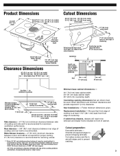
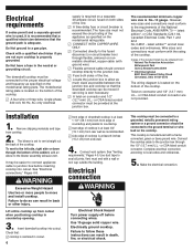
....9 cm) - 30" (76.2 cm) model 35-1/2" (90.2 cm) - 36" (91.4 cm) model cutout width 21" (53.3 cm) cutout depth 2-15/16" (74.6 mm) burner box depth 15-5/8" (39.6 cm) blower housing depth 3-ft. (91.4 cm) long power supply cable factory installed. Motor/blower clearance - 2" (51 mm) minimum clearance between side of cooktop and side...
....9 cm) - 30" (76.2 cm) model 35-1/2" (90.2 cm) - 36" (91.4 cm) model cutout width 21" (53.3 cm) cutout depth 2-15/16" (74.6 mm) burner box depth 15-5/8" (39.6 cm) blower housing depth 3-ft. (91.4 cm) long power supply cable factory installed. Motor/blower clearance - 2" (51 mm) minimum clearance between side of cooktop and side...
Installation Instructions
Page 4
...than one elbow is recommended. Venting methods 9-5/8" (24.4 cm) - 30" (76.2 cm) model 13-5/16" (33.8 cm) - 36" (91.4 cm) model 9-3/4" (24.8 cm) hole in rear or side of cabinet 17" (43.2 cm) The cooktop may be used. • If vent length is not reduced and ...that reduces airflow.) ࠜ Do Not use a 5" (12.7 cm) elbow in "Venting methods" below . inside wall cabinet outside wall cabinet peninsula or island peninsula 3-1/4" x 10" (8.3 x 25.4 cm) transition elbow inside wall to the outside . Do not use 4-inch...
...than one elbow is recommended. Venting methods 9-5/8" (24.4 cm) - 30" (76.2 cm) model 13-5/16" (33.8 cm) - 36" (91.4 cm) model 9-3/4" (24.8 cm) hole in rear or side of cabinet 17" (43.2 cm) The cooktop may be used. • If vent length is not reduced and ...that reduces airflow.) ࠜ Do Not use a 5" (12.7 cm) elbow in "Venting methods" below . inside wall cabinet outside wall cabinet peninsula or island peninsula 3-1/4" x 10" (8.3 x 25.4 cm) transition elbow inside wall to the outside . Do not use 4-inch...
Installation Instructions
Page 6
... parallel to countertop. rear edge of cooktop is at least 6 inches (15.2 cm) from cutout when positioning cooktop in the neutral or grounding circuit. Failure to do so can result in death, fire, or electrical shock. Check that: cooktop is ever necessary. ࠜ A twist-on...on a separate 30-ampere circuit, fused on the model/serial rating plate. ࠜ CONNECT WITH COPPER WIRE ONLY. ࠜ Connected directly to the fused disconnect (or circuit breaker box) through flexible, armored or nonmetallic sheathed, copper cable (with the rating of the cooktop. Remove shipping ...
... parallel to countertop. rear edge of cooktop is at least 6 inches (15.2 cm) from cutout when positioning cooktop in the neutral or grounding circuit. Failure to do so can result in death, fire, or electrical shock. Check that: cooktop is ever necessary. ࠜ A twist-on...on a separate 30-ampere circuit, fused on the model/serial rating plate. ࠜ CONNECT WITH COPPER WIRE ONLY. ࠜ Connected directly to the fused disconnect (or circuit breaker box) through flexible, armored or nonmetallic sheathed, copper cable (with the rating of the cooktop. Remove shipping ...
Installation Instructions
Page 7
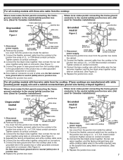
...the junction box inside the cabinet. 3. Replace the junction box cover. Replace the junction box cover. For all cooktop models with three-wire cable from the cooktop: Where local codes Do Not permit connecting the frameground conductor to the neutral (white) junction box wire. (... permit connecting the frame-ground conductor to the white (neutral) wire in junction box. 7. For all cooktop models with four-wire cable from the cooktop. (These cooktops are manufactured with white [neutral] power supply wire and a cabinet-connected bare ground wire factory-crimped together...
...the junction box inside the cabinet. 3. Replace the junction box cover. Replace the junction box cover. For all cooktop models with three-wire cable from the cooktop: Where local codes Do Not permit connecting the frameground conductor to the neutral (white) junction box wire. (... permit connecting the frame-ground conductor to the white (neutral) wire in junction box. 7. For all cooktop models with four-wire cable from the cooktop. (These cooktops are manufactured with white [neutral] power supply wire and a cabinet-connected bare ground wire factory-crimped together...
Installation Instructions
Page 8
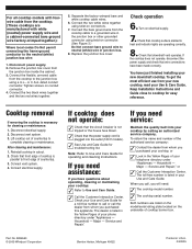
...listed conduit connector. Turn on the underside of your Use and Care Guide. Check that cooktop surface elements heat and indicator lights are listed on the model/serial rating plate located on electrical supply. 7. Household - or ✓ Look in your phone directory under "Appliances - ...Connect the flexible, armored cable from the cooktop to call or call , you have questions about...
...listed conduit connector. Turn on the underside of your Use and Care Guide. Check that cooktop surface elements heat and indicator lights are listed on the model/serial rating plate located on electrical supply. 7. Household - or ✓ Look in your phone directory under "Appliances - ...Connect the flexible, armored cable from the cooktop to call or call , you have questions about...
Use and Care Guide
Page 4
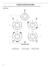
Left rear control knob C. PARTS AND FEATURES This manual covers different models. Right front control knob 4 Control Panel A B E C F D A. Left front control knob D. Right rear control knob F. The cooktop you have purchased may have some or all of the items listed. Downdraft fan knob B. Power on indicator light E.
Left rear control knob C. PARTS AND FEATURES This manual covers different models. Right front control knob 4 Control Panel A B E C F D A. Left front control knob D. Right rear control knob F. The cooktop you have purchased may have some or all of the items listed. Downdraft fan knob B. Power on indicator light E.

Use and Care Guide
Page 5
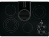
Filter C. Model and serial number plate (located on indicator light H. Control panel I D E H A. Ceramic glass cooktop F D. Power on outside bottom of cooktop) G G. Downdraft vent location E. Stainless steel frame (on some models) 5 Surface cooking area F. Cooktop A B C I . Downdraft vent cover B.
Filter C. Model and serial number plate (located on indicator light H. Control panel I D E H A. Ceramic glass cooktop F D. Power on outside bottom of cooktop) G G. Downdraft vent location E. Stainless steel frame (on some models) 5 Surface cooking area F. Cooktop A B C I . Downdraft vent cover B.
Use and Care Guide
Page 7
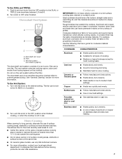
...medium heat settings. Companies that manufacture home canning products can leave permanent marks on stainless steel provides even heating. 7 Aluminum and copper may scratch the cooktop. Cast iron s Heats slowly and evenly. s Heats slowly, but unevenly. s A core or base of a vent cover, filter and a...quickly and evenly. Turn knob to -heavy thickness. Turn vent fan knob to the HI, MED or LO position. 2. s On ceramic glass models, use . To Use DUAL and TRIPLE: 1. Downdraft vent cover B. This allows time for most recently used areas to prevent grease buildup. s...
...medium heat settings. Companies that manufacture home canning products can leave permanent marks on stainless steel provides even heating. 7 Aluminum and copper may scratch the cooktop. Cast iron s Heats slowly and evenly. s Heats slowly, but unevenly. s A core or base of a vent cover, filter and a...quickly and evenly. Turn knob to -heavy thickness. Turn vent fan knob to the HI, MED or LO position. 2. s On ceramic glass models, use . To Use DUAL and TRIPLE: 1. Downdraft vent cover B. This allows time for most recently used areas to prevent grease buildup. s...
Use and Care Guide
Page 8
...-filled scouring pads, abrasive cleaners, Cooktop Polishing Creme, steel-wool pads, gritty washcloths or some models) Clean as soon as cooktop has cooled down . Cleaning Method: Always wipe with a damp paper towel or soft cloth. Cooktop Polishing Creme is also recommended for ...disappears. Heavy soil, dark streaks, specks and discoloration s Cooktop Polishing Creme or nonabrasive cleanser: Rub product into surface with a damp paper towel or soft cloth. Continue rubbing until white film disappears. Cleaning Method: s KitchenAid® Stainless Steel Cleaner & Polish (not included): ...
...-filled scouring pads, abrasive cleaners, Cooktop Polishing Creme, steel-wool pads, gritty washcloths or some models) Clean as soon as cooktop has cooled down . Cleaning Method: Always wipe with a damp paper towel or soft cloth. Cooktop Polishing Creme is also recommended for ...disappears. Heavy soil, dark streaks, specks and discoloration s Cooktop Polishing Creme or nonabrasive cleanser: Rub product into surface with a damp paper towel or soft cloth. Continue rubbing until white film disappears. Cleaning Method: s KitchenAid® Stainless Steel Cleaner & Polish (not included): ...
Use and Care Guide
Page 9
...parts in the United States. Cooktop Care Kit (includes cleaner, protectant, and applicator pads) Order Part Number 31605 Cooktop Scraper (ceramic glass models) Order Part Number 3183488 In the U.S.A. KitchenAid designated service technicians are trained to KitchenAid with : s Features and ... Specialized customer assistance (Spanish speaking, hearing impaired, limited vision, etc.). KitchenAid Canada designated service technicians are trained to KitchenAid Canada with : s Features and specifications on cooktop s Is the cookware the proper size? For further assistance If you need...
...parts in the United States. Cooktop Care Kit (includes cleaner, protectant, and applicator pads) Order Part Number 31605 Cooktop Scraper (ceramic glass models) Order Part Number 3183488 In the U.S.A. KitchenAid designated service technicians are trained to KitchenAid with : s Features and ... Specialized customer assistance (Spanish speaking, hearing impaired, limited vision, etc.). KitchenAid Canada designated service technicians are trained to KitchenAid Canada with : s Features and specifications on cooktop s Is the cookware the proper size? For further assistance If you need...
Use and Care Guide
Page 10
... was purchased. Costs associated with electrical or plumbing codes, or use of consumables or cleaning products not approved by calling KitchenAid. This warranty is void if ...down the following components if defective in materials or workmanship and is reported to KitchenAid within 30 days from unauthorized modifications made to the appliance. 8. Outside the 50 United ...KitchenAid. 5. Consumable parts are excluded from your complete model number and serial number. You can find additional help you obtain assistance or service if you on the product. KITCHENAID® COOKTOP...
... was purchased. Costs associated with electrical or plumbing codes, or use of consumables or cleaning products not approved by calling KitchenAid. This warranty is void if ...down the following components if defective in materials or workmanship and is reported to KitchenAid within 30 days from unauthorized modifications made to the appliance. 8. Outside the 50 United ...KitchenAid. 5. Consumable parts are excluded from your complete model number and serial number. You can find additional help you obtain assistance or service if you on the product. KITCHENAID® COOKTOP...
Parts Diagram
Page 1
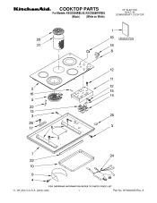
COOKTOP PARTS For Models: KECD806RBL05, KECD806RWW05 (Black) (White on White) 30" ELECTRIC BUILT−IN DOWNDRDAFT COOKTOP 11−08 Litho in U.S.A. (amd) (eeb) 1 Part No. A W10240405 Rev.
COOKTOP PARTS For Models: KECD806RBL05, KECD806RWW05 (Black) (White on White) 30" ELECTRIC BUILT−IN DOWNDRDAFT COOKTOP 11−08 Litho in U.S.A. (amd) (eeb) 1 Part No. A W10240405 Rev.
Parts Diagram
Page 2
COOKTOP PARTS For Models: KECD806RBL05, KECD806RWW05 (Black) (White on White) Illus. No. DESCRIPTION Illus. Part No. Part No. DESCRIPTION 1 Literature Parts 8286240 Installation Instructions 8286427 Wiring Diagram W10162163 Use & Care Guide Safe Cooking Tips 9762761 English W10065852 French 2 Cooktop, Glass 8286948 Black 8286985 White 3 3196537 Screw 4 3177991 Screw 5 Element, Surface 8523698 LR 1200W 8285846...
COOKTOP PARTS For Models: KECD806RBL05, KECD806RWW05 (Black) (White on White) Illus. No. DESCRIPTION Illus. Part No. Part No. DESCRIPTION 1 Literature Parts 8286240 Installation Instructions 8286427 Wiring Diagram W10162163 Use & Care Guide Safe Cooking Tips 9762761 English W10065852 French 2 Cooktop, Glass 8286948 Black 8286985 White 3 3196537 Screw 4 3177991 Screw 5 Element, Surface 8523698 LR 1200W 8285846...
Parts Diagram
Page 3
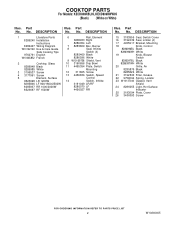
BLOWER UNIT PARTS For Models: KECD806RBL05, KECD806RWW05 (Black) (White on White) Illus. DESCRIPTION 1 W10169759 Bracket, Vent Shield 2 3196537 Screw 3 3192403 Bracket, Blower 4 3367670 Screw (4) 5 488130 Nut (4) 6 9760484 Ring, Inlet 7 9760485 Screen, Inlet 8 9760483 Adapter, Vent 9 W10109930 Blower Motor Assembly (Includes Fan Assembly) FOLLOWING PARTS NOT ILLUSTRATED Miscellaneous 8286642 Tape, Foam W10240405 3 Part No. No.
BLOWER UNIT PARTS For Models: KECD806RBL05, KECD806RWW05 (Black) (White on White) Illus. DESCRIPTION 1 W10169759 Bracket, Vent Shield 2 3196537 Screw 3 3192403 Bracket, Blower 4 3367670 Screw (4) 5 488130 Nut (4) 6 9760484 Ring, Inlet 7 9760485 Screen, Inlet 8 9760483 Adapter, Vent 9 W10109930 Blower Motor Assembly (Includes Fan Assembly) FOLLOWING PARTS NOT ILLUSTRATED Miscellaneous 8286642 Tape, Foam W10240405 3 Part No. No.
Parts Diagram
Page 4
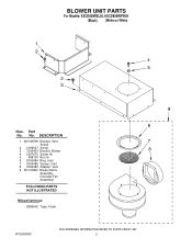
OPTIONAL PARTS For Models: KECD806RBL05, KECD806RWW05 (Black) (White on White) Illus. No. DESCRIPTION FOLLOWING PARTS NOT ILLUSTRATED WIRING HARNESS PARTS 8286419 Harness, Ceran Downdraft 4456859 Harness, Blower/ Switch 4456028 Harness, Jumper 98997 Clip 9760671 Strain Relief 8286423 Conduit, Downdraft 3400015 Screw 4 W10240405 Part No.
OPTIONAL PARTS For Models: KECD806RBL05, KECD806RWW05 (Black) (White on White) Illus. No. DESCRIPTION FOLLOWING PARTS NOT ILLUSTRATED WIRING HARNESS PARTS 8286419 Harness, Ceran Downdraft 4456859 Harness, Blower/ Switch 4456028 Harness, Jumper 98997 Clip 9760671 Strain Relief 8286423 Conduit, Downdraft 3400015 Screw 4 W10240405 Part No.


