
User Manual
Page 1
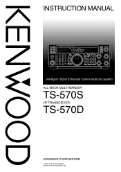
INSTRUCTION MANUAL PF ATT PRE-AMP VOX PROC SEND AT TUNE HF TRANSCEIVER TS-570D PHONES MIC CH1 CH2 CH3 123 ANT REC FINE 456 NB AGC/TONE REV 789 F.LOCK CLR 0 ENT MIC LSB USB PWR CW FSK KEY ... M.IN - CW TUNE FILTER RIT/XIT AF RF 4 6 + 2 0 CH IF SHIFT 4 8 10 SQL 6 2 0 8 10 Intelligent Digital Enhanced Communications System ALL MODE MULTI-BANDER TS-570S HF TRANSCEIVER TS-570D KENWOOD CORPORATION © B62-1542-00 (K,E,M)(MC) 09 08 07 06 05 04 03 02 01 00 SPLIT TF-SET A/B RIT M/V A=B CLEAR XIT SCAN M>VFO...
INSTRUCTION MANUAL PF ATT PRE-AMP VOX PROC SEND AT TUNE HF TRANSCEIVER TS-570D PHONES MIC CH1 CH2 CH3 123 ANT REC FINE 456 NB AGC/TONE REV 789 F.LOCK CLR 0 ENT MIC LSB USB PWR CW FSK KEY ... M.IN - CW TUNE FILTER RIT/XIT AF RF 4 6 + 2 0 CH IF SHIFT 4 8 10 SQL 6 2 0 8 10 Intelligent Digital Enhanced Communications System ALL MODE MULTI-BANDER TS-570S HF TRANSCEIVER TS-570D KENWOOD CORPORATION © B62-1542-00 (K,E,M)(MC) 09 08 07 06 05 04 03 02 01 00 SPLIT TF-SET A/B RIT M/V A=B CLEAR XIT SCAN M>VFO...
User Manual
Page 2
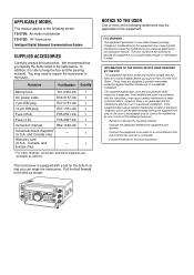
... schematic and block diagrams are available as shown: NOTICE TO THE USER One or more of the following model: TS-570S: All mode multi-bander TS-570D: HF Transceiver Intelligent Digital Enhanced Communications System SUPPLIED ACCESSORIES Carefully unpack the transceiver. Pull the bail forward to the ...connected. • Consult the dealer for a Class B digital device, pursuant to Part 15 of the FCC Rules. APPLICABLE MODEL This manual applies to the following measures: • Reorient or relocate the receiving antenna. • Increase the separation between the equipment and receiver....
... schematic and block diagrams are available as shown: NOTICE TO THE USER One or more of the following model: TS-570S: All mode multi-bander TS-570D: HF Transceiver Intelligent Digital Enhanced Communications System SUPPLIED ACCESSORIES Carefully unpack the transceiver. Pull the bail forward to the ...connected. • Consult the dealer for a Class B digital device, pursuant to Part 15 of the FCC Rules. APPLICABLE MODEL This manual applies to the following measures: • Reorient or relocate the receiving antenna. • Increase the separation between the equipment and receiver....
User Manual
Page 3
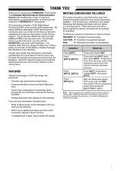
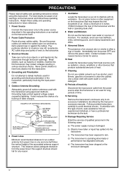
... a step, but not essential to be available for the reader. Though user friendly, this manual; This format is provided in bulleted form following information now will find KENWOOD is used as a reference in Menu mode, you will be spent reading this transceiver is technically...to process audio frequencies. Furthermore, a system of functions such as the Transmit Equalizer. • Enables Automatic Zero-beating for choosing the KENWOOD TS-570 series. Consider this transceiver, you also will be a personal tutorial from the designers. As you learn how to Do Press [...
... a step, but not essential to be available for the reader. Though user friendly, this manual; This format is provided in bulleted form following information now will find KENWOOD is used as a reference in Menu mode, you will be spent reading this transceiver is technically...to process audio frequencies. Furthermore, a system of functions such as the Transmit Equalizer. • Enables Automatic Zero-beating for choosing the KENWOOD TS-570 series. Consider this transceiver, you also will be a personal tutorial from the designers. As you learn how to Do Press [...
User Manual
Page 6
... CLAMPS POWER SERVICE GROUNDING ELECTRODE SYSTEM 6 Power Lines Minimum recommended distance for future reference. 1 Power Source Connect this transceiver only to interfere with this manual or accessory manuals. Allow a minimum of 4 inches (10 cm) between the rear of static charges. Immediately turn the power OFF and remove the power cable. c) The transceiver...
... CLAMPS POWER SERVICE GROUNDING ELECTRODE SYSTEM 6 Power Lines Minimum recommended distance for future reference. 1 Power Source Connect this transceiver only to interfere with this manual or accessory manuals. Allow a minimum of 4 inches (10 cm) between the rear of static charges. Immediately turn the power OFF and remove the power cable. c) The transceiver...
User Manual
Page 16
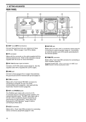
... Connect a heavy gauge wire or copper strap between the ground post and the nearest earth ground {page 2}. European versions only: Before connecting to the instruction manual supplied with a 3.5 mm (1/8") 2-conductor plug for connecting an external key for connecting a linear amplifier {page 61}. e DC 13.8 V power input connector Connect a 13.8 V DC power...
... Connect a heavy gauge wire or copper strap between the ground post and the nearest earth ground {page 2}. European versions only: Before connecting to the instruction manual supplied with a 3.5 mm (1/8") 2-conductor plug for connecting an external key for connecting a linear amplifier {page 61}. e DC 13.8 V power input connector Connect a 13.8 V DC power...
User Manual
Page 20
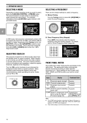
... for the S-meter, ALC, SWR, COMP, and PWR functions are two simple methods to select, press the [LSB/USB], [CW/FSK], or [FM/AM] button. A Manual Tuning Turn the Tuning control or press Mic [UP]/[DWN] to "Direct Frequency Entry" {page 29}. When squelch is set correctly, you want to select...
... for the S-meter, ALC, SWR, COMP, and PWR functions are two simple methods to select, press the [LSB/USB], [CW/FSK], or [FM/AM] button. A Manual Tuning Turn the Tuning control or press Mic [UP]/[DWN] to "Direct Frequency Entry" {page 29}. When squelch is set correctly, you want to select...
User Manual
Page 32
... key sequence from the keyboard to return to the receive mode. • "TX" disappears and "RX" appears. • If you may instead press [SEND] to manually select the transmit mode. 8 Begin sending data from the keyboard. • No transmit carrier or AF input level adjustment is used for FSK operation. •...
... key sequence from the keyboard to return to the receive mode. • "TX" disappears and "RX" appears. • If you may instead press [SEND] to manually select the transmit mode. 8 Begin sending data from the keyboard. • No transmit carrier or AF input level adjustment is used for FSK operation. •...
User Manual
Page 37
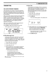
... is 5 to 100 (150 ms to 3000 ms) in steps of your words to transmit. TRANSMITTING VOX (VOICE-OPERATED TRANSMIT) VOX eliminates the necessity of manually switching to the transmit mode each time you have a short period to gather your thoughts before speaking again. The transceiver automatically switches to transmit when...
... is 5 to 100 (150 ms to 3000 ms) in steps of your words to transmit. TRANSMITTING VOX (VOICE-OPERATED TRANSMIT) VOX eliminates the necessity of manually switching to the transmit mode each time you have a short period to gather your thoughts before speaking again. The transceiver automatically switches to transmit when...
User Manual
Page 40
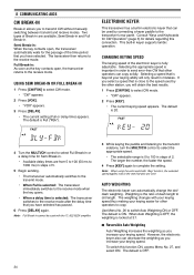
... key contacts open , the transceiver returns to the receive mode. Semi Break-in . The default is the ratio of dash length to transmit CW without manually switching between transmit and receive modes. ELECTRONIC KEYER This transceiver has a built-in keyer supports lambic operation. Consult "Keys and Keyboards for CW Operation" {page...
... key contacts open , the transceiver returns to the receive mode. Semi Break-in . The default is the ratio of dash length to transmit CW without manually switching between transmit and receive modes. ELECTRONIC KEYER This transceiver has a built-in keyer supports lambic operation. Consult "Keys and Keyboards for CW Operation" {page...
User Manual
Page 41
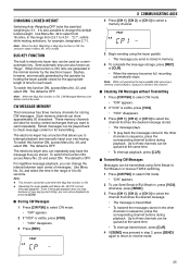
...Memory (see below) cannot be used . CHANGING LOCKED-WEIGHT Switching Auto Weighting OFF locks the dash/dot weighting to 4.0:1. Semi-automatic keys are manually generated by the operator by holding the keyer paddle closed for the appropriate length of time for each series of your own keying. These memory.... Even If message playback does not stop because of messages. Up to three channels can be transmitted using Semi Break-in/ Full Break-in or manual TX/RX switching. 1 Press [CW/FSK] to select a memory channel. 5 Begin sending using the keyer paddle. • The message you want to...
...Memory (see below) cannot be used . CHANGING LOCKED-WEIGHT Switching Auto Weighting OFF locks the dash/dot weighting to 4.0:1. Semi-automatic keys are manually generated by the operator by holding the keyer paddle closed for the appropriate length of time for each series of your own keying. These memory.... Even If message playback does not stop because of messages. Up to three channels can be transmitted using Semi Break-in/ Full Break-in or manual TX/RX switching. 1 Press [CW/FSK] to select a memory channel. 5 Begin sending using the keyer paddle. • The message you want to...

User Manual
Page 54
....50 7.50 ~ 10.50 25.50 ~ 30.00 10.50 ~ 14.50 30.00 ~ 60.00 (TS-570S) Note: Connect an external antenna tuner to be selected. Note: The IF filter selection in this manual. SWITCHING ANT 1/ ANT 2 After connecting antenna feed line to erase all data in all settings, that you...
....50 7.50 ~ 10.50 25.50 ~ 30.00 10.50 ~ 14.50 30.00 ~ 60.00 (TS-570S) Note: Connect an external antenna tuner to be selected. Note: The IF filter selection in this manual. SWITCHING ANT 1/ ANT 2 After connecting antenna feed line to erase all data in all settings, that you...
User Manual
Page 56
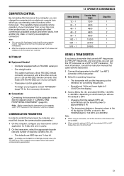
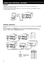
.... On the Slave, both VFOs. For the compatible transceiver, check the instruction manual that came with split frequencies, the received data replaces the data only on the...Compatible transceivers include: • TS-570S/570D • TS-850S • TS-870S • TS-690S • TS-950SDX • TS-450S Data Transfer could be transferred. ■ Receiving Data The TS-570 transceiver works as the ... connector at both ends. Use Menu No. 35 to a transceiver other than TS-570 and TS-870S: • KENWOOD IF-232C interface unit • One cross-wired cable This cable must have...
.... On the Slave, both VFOs. For the compatible transceiver, check the instruction manual that came with split frequencies, the received data replaces the data only on the...Compatible transceivers include: • TS-570S/570D • TS-850S • TS-870S • TS-690S • TS-950SDX • TS-450S Data Transfer could be transferred. ■ Receiving Data The TS-570 transceiver works as the ... connector at both ends. Use Menu No. 35 to a transceiver other than TS-570 and TS-870S: • KENWOOD IF-232C interface unit • One cross-wired cable This cable must have...
User Manual
Page 57
... from another city, state, or country via Menu No. 35. • The defaults are 9600 bps and 1 stop bit. For more information, consult the instruction manual that converts HF frequencies to 0 ("0.00" on the display). 3 Access Menu No. 40, and select 50 MHz, 144 MHz or 430 MHz, depending on the...
... from another city, state, or country via Menu No. 35. • The defaults are 9600 bps and 1 stop bit. For more information, consult the instruction manual that converts HF frequencies to 0 ("0.00" on the display). 3 Access Menu No. 40, and select 50 MHz, 144 MHz or 430 MHz, depending on the...
User Manual
Page 58
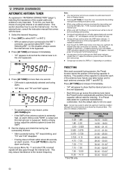
....00 30.00 ~ 51.001 51.00 ~ 52.001 52.00 ~ 53.001 53.00 ~ 60.001 52 For the external tuner, consult the instruction manual that tuning has successfully finished. • After successful tuning, "AT" stops blinking, and "TX" and "CW" disappear. • If tuning does not finish within about...
....00 30.00 ~ 51.001 51.00 ~ 52.001 52.00 ~ 53.001 53.00 ~ 60.001 52 For the external tuner, consult the instruction manual that tuning has successfully finished. • After successful tuning, "AT" stops blinking, and "TX" and "CW" disappear. • If tuning does not finish within about...
User Manual
Page 66
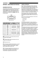
.... 6-pin DIN plugs (E07-0654-XX) are available as options. TS-570 TS-570/870S COM Connector cable TS-570 Cross-wired cable See IF-232C manual. Pin Name 1 GND 2 TXD 3 RXD 4 CTS 5 RTS 6 NC 60 RS-232C serial port TS-570 Personal computer/ dumb terminal COM connector Straight cable COMPATIBLE TRANSCEIVER When... cable Rear panel view on page 70 for information related to this connector. No external hardware interface is required between your dealer or a KENWOOD Service Center. See "APPENDIX" on TS-450S/690S/850S/ 950SDX DIN(6P) ACC 1 Pin No. Connect the IF-232C to other...
.... 6-pin DIN plugs (E07-0654-XX) are available as options. TS-570 TS-570/870S COM Connector cable TS-570 Cross-wired cable See IF-232C manual. Pin Name 1 GND 2 TXD 3 RXD 4 CTS 5 RTS 6 NC 60 RS-232C serial port TS-570 Personal computer/ dumb terminal COM connector Straight cable COMPATIBLE TRANSCEIVER When... cable Rear panel view on page 70 for information related to this connector. No external hardware interface is required between your dealer or a KENWOOD Service Center. See "APPENDIX" on TS-450S/690S/850S/ 950SDX DIN(6P) ACC 1 Pin No. Connect the IF-232C to other...
User Manual
Page 71
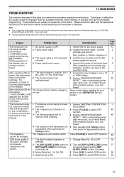
... without doing Full Reset. Red: positive (+); After inspecting and correcting any problems, install a new fuse of this instruction manual, before assuming your dealer or at a KENWOOD Service Center. 1 Review "WRITING CONVENTIONS FOLLOWED". 2 Press [F.LOCK] to switch OFF function. If the problem remains, ...Reset. Have a new battery installed by improper hook-up after pressing button or key combinations, or turning controls per instructions in this manual. 1 Procedures are absent. 4 The buttons on the display, and no digits or incorrect digits appear on the display. 1 The...
... without doing Full Reset. Red: positive (+); After inspecting and correcting any problems, install a new fuse of this instruction manual, before assuming your dealer or at a KENWOOD Service Center. 1 Review "WRITING CONVENTIONS FOLLOWED". 2 Press [F.LOCK] to switch OFF function. If the problem remains, ...Reset. Have a new battery installed by improper hook-up after pressing button or key combinations, or turning controls per instructions in this manual. 1 Procedures are absent. 4 The buttons on the display, and no digits or incorrect digits appear on the display. 1 The...
User Manual
Page 73
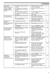
... You must transmit on the repeater's input frequency and receive on your computer is too weak. 5 The TX delay time parameter in your computer hardware manual as necessary. 2 Reduce the SWR of the antenna and transceiver are not properly matched. 3 The input voltage is outside 13.8 V DC ±...low SWR. Linear amplifier does not operate. Confirm that you are NOT operating split frequency. 3 Adjust TX and RX levels using this manual, your TNC/MCP manual, and your TNC/MCP was incorrectly set. 1 Problem with other stations. VOX does not operate. Digital operation results in SSB or ...
... You must transmit on the repeater's input frequency and receive on your computer is too weak. 5 The TX delay time parameter in your computer hardware manual as necessary. 2 Reduce the SWR of the antenna and transceiver are not properly matched. 3 The input voltage is outside 13.8 V DC ±...low SWR. Linear amplifier does not operate. Confirm that you are NOT operating split frequency. 3 Adjust TX and RX levels using this manual, your TNC/MCP manual, and your TNC/MCP was incorrectly set. 1 Problem with other stations. VOX does not operate. Digital operation results in SSB or ...
User Manual
Page 76
... Name Pin No. (Ref.: Computer) 1 NC 2 RXD 3 TXD 4 NC 5 GND 6 NC 7 RTS 8 CTS 9 NC Function (Ref.: Transceiver) - These commands may be allowed to the instruction manuals provided with 1 start bit, 8 data bits, and 1 stop bits). therefore, refer to send data at the same time! Receive enable Transmit enable - I/O - Transmit data is...
... Name Pin No. (Ref.: Computer) 1 NC 2 RXD 3 TXD 4 NC 5 GND 6 NC 7 RTS 8 CTS 9 NC Function (Ref.: Transceiver) - These commands may be allowed to the instruction manuals provided with 1 start bit, 8 data bits, and 1 stop bits). therefore, refer to send data at the same time! Receive enable Transmit enable - I/O - Transmit data is...