

User Manual
Page 4
... CONNECTION 2 REPLACING FUSES 2 ACCESSORY CONNECTIONS 3 FRONT PANEL 3 Headphones (PHONES 3 Microphone (MIC 3 REAR PANEL 3 External Speaker (EXT SP 3 Keys and Keyboards for CW Operation (PADDLE and KEY 3 CHAPTER 2 YOUR FIRST QSO 4 RECEIVING 4 TRANSMITTING 5 CHAPTER 3 GETTING ACQUAINTED 6 FRONT PANEL 6 MICROPHONE 9 REAR PANEL 10 DISPLAY 11 CHAPTER 4 OPERATING BASICS 13 SWITCHING POWER ON/OFF 13 ADJUSTING VOLUME 13 AUDIO FREQUENCY (AF) GAIN 13 RADIO FREQUENCY (RF) GAIN 13 SELECTING VFO A OR VFO B 13 SELECTING A BAND 13 SELECTING A MODE 14 ADJUSTING SQUELCH...
... CONNECTION 2 REPLACING FUSES 2 ACCESSORY CONNECTIONS 3 FRONT PANEL 3 Headphones (PHONES 3 Microphone (MIC 3 REAR PANEL 3 External Speaker (EXT SP 3 Keys and Keyboards for CW Operation (PADDLE and KEY 3 CHAPTER 2 YOUR FIRST QSO 4 RECEIVING 4 TRANSMITTING 5 CHAPTER 3 GETTING ACQUAINTED 6 FRONT PANEL 6 MICROPHONE 9 REAR PANEL 10 DISPLAY 11 CHAPTER 4 OPERATING BASICS 13 SWITCHING POWER ON/OFF 13 ADJUSTING VOLUME 13 AUDIO FREQUENCY (AF) GAIN 13 RADIO FREQUENCY (RF) GAIN 13 SELECTING VFO A OR VFO B 13 SELECTING A BAND 13 SELECTING A MODE 14 ADJUSTING SQUELCH...
User Manual
Page 5
... SETTINGS 48 PARTIAL RESET 48 FULL RESET 48 SWITCHING ANT 1/ ANT 2 48 FREQUENCY LOCK FUNCTION 48 BEEP FUNCTION 49 DISPLAY DIMMER 49 PROGRAM FUNCTION BUTTON 49 QUICK DATA TRANSFER 50 SETTING UP 50 Equipment Needed 50 Connections 50 USING QUICK TRANSFER 50 Transferring Data 50 Receiving Data 50 COMPUTER CONTROL 51 SETTING UP 51 Equipment Needed 51 Connections 51 COMMUNICATION PARAMETERS 51 USING A TRANSVERTER 51 AUTOMATIC ANTENNA TUNER 52 PRESETTING 52 DRU-3A DIGITAL RECORDING UNIT (OPTIONAL 53 RECORDING...
... SETTINGS 48 PARTIAL RESET 48 FULL RESET 48 SWITCHING ANT 1/ ANT 2 48 FREQUENCY LOCK FUNCTION 48 BEEP FUNCTION 49 DISPLAY DIMMER 49 PROGRAM FUNCTION BUTTON 49 QUICK DATA TRANSFER 50 SETTING UP 50 Equipment Needed 50 Connections 50 USING QUICK TRANSFER 50 Transferring Data 50 Receiving Data 50 COMPUTER CONTROL 51 SETTING UP 51 Equipment Needed 51 Connections 51 COMMUNICATION PARAMETERS 51 USING A TRANSVERTER 51 AUTOMATIC ANTENNA TUNER 52 PRESETTING 52 DRU-3A DIGITAL RECORDING UNIT (OPTIONAL 53 RECORDING...
User Manual
Page 6
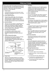
... accessory installations described by lightning. Metal objects, such as hairpins or needles, inserted into this manual or accessory manuals. Do not place books or other devices that may contact voltages resulting in serious electrical shocks. Immediately turn the power OFF and remove the power cable. Follow provided instructions carefully to rain. EXAMPLE OF ANTENNA GROUNDING GROUND CLAMP ANTENNA LEAD IN WIRE ANTENNA DISCHARGE UNIT ELECTRIC SERVICE...
... accessory installations described by lightning. Metal objects, such as hairpins or needles, inserted into this manual or accessory manuals. Do not place books or other devices that may contact voltages resulting in serious electrical shocks. Immediately turn the power OFF and remove the power cable. Follow provided instructions carefully to rain. EXAMPLE OF ANTENNA GROUNDING GROUND CLAMP ANTENNA LEAD IN WIRE ANTENNA DISCHARGE UNIT ELECTRIC SERVICE...
User Manual
Page 8
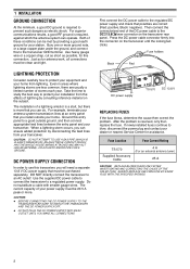
... PIPE FOR A GROUND. Use the supplied DC power cable to connect the transceiver to an AC outlet! Then connect the connectorized end of a lightning arrestor is a start, but there is required, against which the antenna system can do. If newly installed fuses continue to a good outside your transceiver. Fuse Location Fuse Current Rating TS-570 Supplied Accessory Cable 4 A (For an external antenna tuner) 25 A CAUTION: REPLACE BLOWN FUSES ONLY AFTER INVESTIGATING...
... PIPE FOR A GROUND. Use the supplied DC power cable to connect the transceiver to an AC outlet! Then connect the connectorized end of a lightning arrestor is a start, but there is required, against which the antenna system can do. If newly installed fuses continue to a good outside your transceiver. Fuse Location Fuse Current Rating TS-570 Supplied Accessory Cable 4 A (For an external antenna tuner) 25 A CAUTION: REPLACE BLOWN FUSES ONLY AFTER INVESTIGATING...

User Manual
Page 9
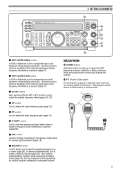
...(STBY) uGND(MIC) yNC t8 V(10 mA max) Microphone MIC connector (Front view) External speaker TS-570 Ground + Ground Dash Dot • Straight key • Bug • Electronic keyer • MCP CW output • Paddle 3 Use a shielded cable between 250 Ω and 600 Ω. Use a 6.0 mm (1/4") diameter, 2-conductor (mono) or 3-conductor (stereo) plug. ■ Microphone (MIC) To communicate in the voice modes, connect to the MIC connector a microphone having 4 to connect both a paddle...
...(STBY) uGND(MIC) yNC t8 V(10 mA max) Microphone MIC connector (Front view) External speaker TS-570 Ground + Ground Dash Dot • Straight key • Bug • Electronic keyer • MCP CW output • Paddle 3 Use a shielded cable between 250 Ω and 600 Ω. Use a 6.0 mm (1/4") diameter, 2-conductor (mono) or 3-conductor (stereo) plug. ■ Microphone (MIC) To communicate in the voice modes, connect to the MIC connector a microphone having 4 to connect both a paddle...
User Manual
Page 15
... control Turn to adjust the audio frequency gain {page 13}. #0 RF control Turn to adjust the radio frequency gain {page 13}. #1 IF SHIFT control Turn to improve readability of the receive pass band. Also used for selecting Menu numbers when accessing the Menu mode {page 16}, and as a selector to choose settings for muting ("squelching") the speaker output when no receive signal is held down the VFO frequency, memory channels, or Menu selections. MICROPHONE q UP/DWN buttons Use these buttons to receive mode. Press...
... control Turn to adjust the audio frequency gain {page 13}. #0 RF control Turn to adjust the radio frequency gain {page 13}. #1 IF SHIFT control Turn to improve readability of the receive pass band. Also used for selecting Menu numbers when accessing the Menu mode {page 16}, and as a selector to choose settings for muting ("squelching") the speaker output when no receive signal is held down the VFO frequency, memory channels, or Menu selections. MICROPHONE q UP/DWN buttons Use these buttons to receive mode. Press...
User Manual
Page 16
... cable supplied with the Quick Data Transfer function {page 60}. European versions only: Before connecting to the internal speaker. e DC 13.8 V power input connector Connect a 13.8 V DC power source {page 2}. Also used with the external antenna tuner. u ACC 2 connector Mates with this tuner for connecting various accessory equipment {pages 61, 62}. Refer to the instruction manual supplied with a 13-pin male DIN connector for more information. i EXT SP jack Mates with a 6.0 mm (1/4") 3-conductor plug for connecting...
... cable supplied with the Quick Data Transfer function {page 60}. European versions only: Before connecting to the internal speaker. e DC 13.8 V power input connector Connect a 13.8 V DC power source {page 2}. Also used with the external antenna tuner. u ACC 2 connector Mates with this tuner for connecting various accessory equipment {pages 61, 62}. Refer to the instruction manual supplied with a 13-pin male DIN connector for more information. i EXT SP jack Mates with a 6.0 mm (1/4") 3-conductor plug for connecting...
User Manual
Page 25
... Semi-automatic key ("Bug") function 22 TX sidetone frequency 20 TX sidetone volume 21 DATA TRANSFER Transfer enable 36 Transfer method 37 DIGITAL OPERATION AF input (MCP/TNC TX) 33 AF output (MCP/TNC RX) 34 Filter bandwidth 32 DISPLAY Brightness 00 DRU-3A DIGITAL RECORDING SYSTEM (DRS) Playback repeat 23 Playback repeat interval 24 Playback volume 25 DIGITAL SIGNAL PROCESSING NR2 time constant 12...
... Semi-automatic key ("Bug") function 22 TX sidetone frequency 20 TX sidetone volume 21 DATA TRANSFER Transfer enable 36 Transfer method 37 DIGITAL OPERATION AF input (MCP/TNC TX) 33 AF output (MCP/TNC RX) 34 Filter bandwidth 32 DISPLAY Brightness 00 DRU-3A DIGITAL RECORDING SYSTEM (DRS) Playback repeat 23 Playback repeat interval 24 Playback volume 25 DIGITAL SIGNAL PROCESSING NR2 time constant 12...

User Manual
Page 33
... meter reflects. 7 SPECIALIZED COMMUNICATING 6 Exit the calibrate mode. • "TX" disappears and "RX" appears. 7 Use Menu No. 34 to select the appropriate AF output level. • The AF control cannot be used . In some countries, F2 modulation at 1200 bps may be good starting places when searching for this adjustment. 8 Send commands and data. • The transceiver will briefly transmit each band various modes...
... meter reflects. 7 SPECIALIZED COMMUNICATING 6 Exit the calibrate mode. • "TX" disappears and "RX" appears. 7 Use Menu No. 34 to select the appropriate AF output level. • The AF control cannot be used . In some countries, F2 modulation at 1200 bps may be good starting places when searching for this adjustment. 8 Send commands and data. • The transceiver will briefly transmit each band various modes...

User Manual
Page 35
... AM mode. COMMUNICATING AIDS RECEIVING SELECTING YOUR FREQUENCY In addition to turning the Tuning control or pressing Mic [UP]/[DWN], there are multiples of the frequency step size. Pressing one of those digits will cause that is not displayed. ◆ Attempting to enter a frequency that digit to 99 that have Start and End frequencies stored, the receive frequency can be changed by using Direct Frequency Entry within the programmed range. ■ Using 1 MHz...
... AM mode. COMMUNICATING AIDS RECEIVING SELECTING YOUR FREQUENCY In addition to turning the Tuning control or pressing Mic [UP]/[DWN], there are multiples of the frequency step size. Pressing one of those digits will cause that is not displayed. ◆ Attempting to enter a frequency that digit to 99 that have Start and End frequencies stored, the receive frequency can be changed by using Direct Frequency Entry within the programmed range. ■ Using 1 MHz...
User Manual
Page 40
... selectable range is 0 to 100 in : When the key contacts open , the transceiver returns to the receive mode. This built-in order to send error-free CW that other operators to copy. Note: Full Break-in cannot be used with your keying speed thus making your keying speed. When Auto Weighting is OFF, the weighting is locked at 3:1. ■ Reversible Auto Weighting Auto Weighting...
... selectable range is 0 to 100 in : When the key contacts open , the transceiver returns to the receive mode. This built-in order to send error-free CW that other operators to copy. Note: Full Break-in cannot be used with your keying speed thus making your keying speed. When Auto Weighting is OFF, the weighting is locked at 3:1. ■ Reversible Auto Weighting Auto Weighting...

User Manual
Page 45
... may store the frequency where you find the transceiver powers-up with default settings, and VFO and memory channel data is overwritten. 39 The data that you store: • Simplex channels: RX frequency = TX frequency • Split-frequency channels: RX frequency ≠ TX frequency Memory channels 90 to show which VFO is listed below: Parameter RX frequency TX frequency Mode for RX Mode for programming VFO tuning ranges and scan ranges. Note: When RIT...
... may store the frequency where you find the transceiver powers-up with default settings, and VFO and memory channel data is overwritten. 39 The data that you store: • Simplex channels: RX frequency = TX frequency • Split-frequency channels: RX frequency ≠ TX frequency Memory channels 90 to show which VFO is listed below: Parameter RX frequency TX frequency Mode for RX Mode for programming VFO tuning ranges and scan ranges. Note: When RIT...

User Manual
Page 47
... Scroll. ■ Temporary Frequency Changes After retrieving frequencies and associated data in Memory Recall mode, you can temporarily change channels. 3 To exit Memory Scroll mode, press [CLR]. • The transceiver re-displays the memory channel or VFO frequency that was last selected appears. 2 Turn the MULTI/CH control, or press Mic [UP] or [DWN] to step through the memory channels. • Entering a 2-digit number such as follows...
... Scroll. ■ Temporary Frequency Changes After retrieving frequencies and associated data in Memory Recall mode, you can temporarily change channels. 3 To exit Memory Scroll mode, press [CLR]. • The transceiver re-displays the memory channel or VFO frequency that was last selected appears. 2 Turn the MULTI/CH control, or press Mic [UP] or [DWN] to step through the memory channels. • Entering a 2-digit number such as follows...

User Manual
Page 52
...; Starting Program Scan switches OFF the RIT and XIT functions. ◆ When in the Conventional memory channels. All-channel Scan Monitors all RX frequencies Group Scan stored in those channels. PROGRAM SCAN Program Scan monitors the range between the start frequency stored in the smallest channel number. ◆ Operating mode can select a maximum of 10 memory channels and sequentially scan the ranges that you store in the channel with that range is used. ◆ When the current receive frequency...
...; Starting Program Scan switches OFF the RIT and XIT functions. ◆ When in the Conventional memory channels. All-channel Scan Monitors all RX frequencies Group Scan stored in those channels. PROGRAM SCAN Program Scan monitors the range between the start frequency stored in the smallest channel number. ◆ Operating mode can select a maximum of 10 memory channels and sequentially scan the ranges that you store in the channel with that range is used. ◆ When the current receive frequency...

User Manual
Page 53
... number that contain frequency data. 1 Select Time-operated or Carrier-operated via Menu No. 10. 2 Press [MR] to enter Memory Recall mode. 3 Turn the SQL control to adjust the squelch to the threshold. 4 Press and hold down [SCAN] then, using Group Scan, enter all settings, that you have turned the SQL control clockwise far beyond the squelch threshold, Scan may fail to select either a short time (Time-operated mode) or until the signal drops (Carrier-operated mode). Use Menu...
... number that contain frequency data. 1 Select Time-operated or Carrier-operated via Menu No. 10. 2 Press [MR] to enter Memory Recall mode. 3 Turn the SQL control to adjust the squelch to the threshold. 4 Press and hold down [SCAN] then, using Group Scan, enter all settings, that you have turned the SQL control clockwise far beyond the squelch threshold, Scan may fail to select either a short time (Time-operated mode) or until the signal drops (Carrier-operated mode). Use Menu...

User Manual
Page 54
... channels. menu settings, antenna tuner preset data, etc. OPERATOR CONVENIENCES MICROPROCESSOR RESET If your transceiver seems to the ANT 1 connector only. SWITCHING ANT 1/ ANT 2 After connecting antenna feed line to the instructions in Menu mode. ◆ After activating Frequency Lock, you select the same band, the same setting will not be selected. Each time you can still change the transmit frequency with the Tuning control while using the TF-SET function. ◆ After activating Frequency Lock...
... channels. menu settings, antenna tuner preset data, etc. OPERATOR CONVENIENCES MICROPROCESSOR RESET If your transceiver seems to the ANT 1 connector only. SWITCHING ANT 1/ ANT 2 After connecting antenna feed line to the instructions in Menu mode. ◆ After activating Frequency Lock, you select the same band, the same setting will not be selected. Each time you can still change the transmit frequency with the Tuning control while using the TF-SET function. ◆ After activating Frequency Lock...
User Manual
Page 56
... appropriate operation to select these parameters. For the compatible transceiver, check the instruction manual that is searching for new contest multipliers can receive data using another compatible transceiver. The Slave can quickly transfer a frequency over to the Slave transceiver. 1 Switch ON the Transfer function on how to a transceiver other than TS-570 and TS-870S: • KENWOOD IF-232C interface unit • One cross-wired cable This cable must have a 6-pin...
... appropriate operation to select these parameters. For the compatible transceiver, check the instruction manual that is searching for new contest multipliers can receive data using another compatible transceiver. The Slave can quickly transfer a frequency over to the Slave transceiver. 1 Switch ON the Transfer function on how to a transceiver other than TS-570 and TS-870S: • KENWOOD IF-232C interface unit • One cross-wired cable This cable must have a 6-pin...
User Manual
Page 71
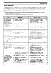
... key combinations, or turning controls per instructions in this table are commonly encountered operational malfunctions. If the problem remains, do a Partial Reset. SSB audio quality is lost , do a Full Reset. 4 Stop operating the Tuning control, then press the appropriate buttons. TROUBLESHOOTING 16 MAINTENANCE The problems described in this manual. 1 Procedures are unavailable while operating the Tuning control. Note: ◆ Due to 16 V batter.y 2 Review "MICROPROCESSOR RESET". After switching ON the power...
... key combinations, or turning controls per instructions in this table are commonly encountered operational malfunctions. If the problem remains, do a Partial Reset. SSB audio quality is lost , do a Full Reset. 4 Stop operating the Tuning control, then press the appropriate buttons. TROUBLESHOOTING 16 MAINTENANCE The problems described in this manual. 1 Procedures are unavailable while operating the Tuning control. Note: ◆ Due to 16 V batter.y 2 Review "MICROPROCESSOR RESET". After switching ON the power...
User Manual
Page 73
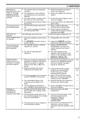
... antenna gain. 5 Set the TNC/MCP TX delay time to ON. 2 Inspect the REMOTE connector wiring and correct as necessary. 1 Review "FM REPEATER OPERATION" and select the correct frequency and type of subtone. 2 You must transmit on the repeater's input frequency and receive on your computer is too weak. 5 The TX delay time parameter in your terminal program do not match transceiver parameters. 3 The serial port...
... antenna gain. 5 Set the TNC/MCP TX delay time to ON. 2 Inspect the REMOTE connector wiring and correct as necessary. 1 Review "FM REPEATER OPERATION" and select the correct frequency and type of subtone. 2 You must transmit on the repeater's input frequency and receive on your computer is too weak. 5 The TX delay time parameter in your terminal program do not match transceiver parameters. 3 The serial port...
User Manual
Page 88
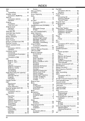
... Cross Reference 19 Description 16 Meter 14 Microphone Compatible 3 Connector (MIC 3 Gain 15 Operation 9 Noise Blanker 36 Reduction 38 Optional Accessories Available 56 Installation 57 Packet Connection (ACC 2 62 Operation 27 PacTOR Connection (ACC 2 62 Operation 27 Partial Reset 48 Power Connecting DC 2 Switching ON/OFF 13 Transmit Output 15 Program Scan 46 Programmable Buttons 49 VFO 43 Quick Data Transfer Equipment, Compatible .......... 50 Equipment, Connection .......... 60 Equipment, Needed 50 Using 50 Reset Full 48 Partial 48...
... Cross Reference 19 Description 16 Meter 14 Microphone Compatible 3 Connector (MIC 3 Gain 15 Operation 9 Noise Blanker 36 Reduction 38 Optional Accessories Available 56 Installation 57 Packet Connection (ACC 2 62 Operation 27 PacTOR Connection (ACC 2 62 Operation 27 Partial Reset 48 Power Connecting DC 2 Switching ON/OFF 13 Transmit Output 15 Program Scan 46 Programmable Buttons 49 VFO 43 Quick Data Transfer Equipment, Compatible .......... 50 Equipment, Connection .......... 60 Equipment, Needed 50 Using 50 Reset Full 48 Partial 48...


