

Operation Manual
Page 3
... Digital Signal Processing (DSP) units to simplify instructions and avoid unnecessary repetition. in Menu mode, you will see scrolling messages on the display that tell you what you change the Menu No. Accessory Quantity Part Number TS-2000 TS-2000X TS-B2000 Microphone T91-0352-XX 1 1 DC power cable E30-3157-XX 1 1 7-pin DIN plug E07-0751-XX 1 1 8-pin DIN plug E07-0851-XX 1 1 13-pin DIN plug E07-1351-XX 1 1 Fuse (25A) F05-2531-XX 1 1 Fuse...
... Digital Signal Processing (DSP) units to simplify instructions and avoid unnecessary repetition. in Menu mode, you will see scrolling messages on the display that tell you what you change the Menu No. Accessory Quantity Part Number TS-2000 TS-2000X TS-B2000 Microphone T91-0352-XX 1 1 DC power cable E30-3157-XX 1 1 7-pin DIN plug E07-0751-XX 1 1 8-pin DIN plug E07-0851-XX 1 1 13-pin DIN plug E07-1351-XX 1 1 Fuse (25A) F05-2531-XX 1 1 Fuse...

Operation Manual
Page 6
... POWER SUPPLY CONNECTION 2 UTILIZING THE BAIL (TS-2000 (X) ONLY 2 REPLACING FUSES 2 ACCESSORY CONNECTIONS 3 FRONT PANEL 3 Headphones (PHONES 3 Microphone (MIC 3 REAR PANEL 3 External Speakers (EXT.SP1/ EXT.SP2) ......... 3 Keys for CW (PADDLE and KEY 3 CHAPTER 2 YOUR FIRST QSO (HF/ 50MHz band) RECEIVING 4 TRANSMITTING 5 CHAPTER 3 YOUR FIRST QSO (VHF/ UHF band) RECEIVING 6 TRANSMITTING 7 CHAPTER 4 GETTING ACQUAINTED FRONT PANEL 8 REAR PANEL 13 DISPLAY 14 MICROPHONE 17 CHAPTER 5 OPERATING BASICS SWITCHING POWER ON/OFF 18 ADJUSTING VOLUME 18 AUDIO FREQUENCY (AF) GAIN 18 RADIO...
... POWER SUPPLY CONNECTION 2 UTILIZING THE BAIL (TS-2000 (X) ONLY 2 REPLACING FUSES 2 ACCESSORY CONNECTIONS 3 FRONT PANEL 3 Headphones (PHONES 3 Microphone (MIC 3 REAR PANEL 3 External Speakers (EXT.SP1/ EXT.SP2) ......... 3 Keys for CW (PADDLE and KEY 3 CHAPTER 2 YOUR FIRST QSO (HF/ 50MHz band) RECEIVING 4 TRANSMITTING 5 CHAPTER 3 YOUR FIRST QSO (VHF/ UHF band) RECEIVING 6 TRANSMITTING 7 CHAPTER 4 GETTING ACQUAINTED FRONT PANEL 8 REAR PANEL 13 DISPLAY 14 MICROPHONE 17 CHAPTER 5 OPERATING BASICS SWITCHING POWER ON/OFF 18 ADJUSTING VOLUME 18 AUDIO FREQUENCY (AF) GAIN 18 RADIO...

Operation Manual
Page 8
... EQUALIZING RECEIVING AUDIO (SSB/ FM/ AM 78 SEPARATE SPEAKER OUTPUT 78 S-METER SQUELCH 78 SQUELCH HANG TIME 78 TIME-OUT TIMER 78 vi TNC 79 TRANSVERTER 79 TX MONITOR 79 TX POWER 79 QUICK DATA TRANSFER 80 SETTING UP 80 Equipment Needed 80 Connections 80 USING QUICK TRANSFER 80 Transferring Data 80 Receiving Data 80 COMPUTER CONTROL 81 SETTING UP 81 Equipment Needed 81 Connections 81 COMMUNICATION PARAMETERS 81 REMOTE MICROPHONE CONTROLLER 81 WIRELESS REMOTE CONTROL (K-type ONLY) .. 82 PREPARATION 82 CONTROL OPERATION...
... EQUALIZING RECEIVING AUDIO (SSB/ FM/ AM 78 SEPARATE SPEAKER OUTPUT 78 S-METER SQUELCH 78 SQUELCH HANG TIME 78 TIME-OUT TIMER 78 vi TNC 79 TRANSVERTER 79 TX MONITOR 79 TX POWER 79 QUICK DATA TRANSFER 80 SETTING UP 80 Equipment Needed 80 Connections 80 USING QUICK TRANSFER 80 Transferring Data 80 Receiving Data 80 COMPUTER CONTROL 81 SETTING UP 81 Equipment Needed 81 Connections 81 COMMUNICATION PARAMETERS 81 REMOTE MICROPHONE CONTROLLER 81 WIRELESS REMOTE CONTROL (K-type ONLY) .. 82 PREPARATION 82 CONTROL OPERATION...

Operation Manual
Page 11
.... Install and connect a DC power supply {page 2}. For superior communications results, a good RF ground is more ground rods or a large copper plate under the ground, then connect this entry panel to compensate for your primary HF/ 50 MHz antenna feed line to prevent such dangers as stereo receivers and televisions. Connect VHF (144 MHz), UHF (430/ 440 MHz), and 1.2 GHz (TS-2000/ TS...
.... Install and connect a DC power supply {page 2}. For superior communications results, a good RF ground is more ground rods or a large copper plate under the ground, then connect this entry panel to compensate for your primary HF/ 50 MHz antenna feed line to prevent such dangers as stereo receivers and televisions. Connect VHF (144 MHz), UHF (430/ 440 MHz), and 1.2 GHz (TS-2000/ TS...

Operation Manual
Page 12
... DC power cable to the transceiver's DC power connector. Press the connectors firmly together until the locking tab locks. If newly installed fuses continue to an AC outlet. Do not directly connect the transceiver to blow, disconnect the power plug and contact a KENWOOD service station or your dealer for assistance. Next, connect the DC power cable to the regulated DC power supply; PROTECTIVE COVERS Remove the protective covers from the jacks and connectors...
... DC power cable to the transceiver's DC power connector. Press the connectors firmly together until the locking tab locks. If newly installed fuses continue to an AC outlet. Do not directly connect the transceiver to blow, disconnect the power plug and contact a KENWOOD service station or your dealer for assistance. Next, connect the DC power cable to the regulated DC power supply; PROTECTIVE COVERS Remove the protective covers from the jacks and connectors...

Operation Manual
Page 13
... cable between 250 and 600Ω. Read the "ELECTRONIC KEYER" section {page 42} to be compatible with the internal keyer. 1 INSTALLATION Headphone TS-2000 TS-2000X TS-B2000 MIC q PTT w DOWN e UP r i GND (STBY) u GND (MIC) y NC t 8 V (10 mA max) Microphone MIC connector (Front view) External speaker TS-2000 TS-2000X TS-B2000 GND + GND dash dot • Straight key • Bug key • Electronic keyer • MCP CW output • Paddle 3 Compatible microphones...
... cable between 250 and 600Ω. Read the "ELECTRONIC KEYER" section {page 42} to be compatible with the internal keyer. 1 INSTALLATION Headphone TS-2000 TS-2000X TS-B2000 MIC q PTT w DOWN e UP r i GND (STBY) u GND (MIC) y NC t 8 V (10 mA max) Microphone MIC connector (Front view) External speaker TS-2000 TS-2000X TS-B2000 GND + GND dash dot • Straight key • Bug key • Electronic keyer • MCP CW output • Paddle 3 Compatible microphones...

Operation Manual
Page 18
.../ LOCK A] to switch the Break-in function ON or OFF {page 42}. In CW mode, press to lock all the transceiver keys {page 77}. i AT/ ANT1/2 key Press to adjust the DSP Auto Notch reduction level. Inserting a plug into the jack automatically mutes the audio from the speaker {pages 3, 78}. !0 MIC connector Connect a compatible microphone to this Programmable Function key. Press [FUNC], [A.N./ LEVEL] to activate the internal antenna tuner...
.../ LOCK A] to switch the Break-in function ON or OFF {page 42}. In CW mode, press to lock all the transceiver keys {page 77}. i AT/ ANT1/2 key Press to adjust the DSP Auto Notch reduction level. Inserting a plug into the jack automatically mutes the audio from the speaker {pages 3, 78}. !0 MIC connector Connect a compatible microphone to this Programmable Function key. Press [FUNC], [A.N./ LEVEL] to activate the internal antenna tuner...

Operation Manual
Page 22
... MIC MANUAL N.R. The MULTI/ CH LED lights when the setting(s) can be changed using the MULTI/ CH control. $8 MAIN SQL control Used for muting ("squelching") the speaker, the head phones and AF output on ACC2 (13-pin DIN connector) when no receive signal is present on the main transceiver {page 19}. $9 MAIN AF control Turn to adjust the volume on the main transceiver {page 19}. %0 SUB SQL control Used for muting ("squelching") the speaker, head phone...
... MIC MANUAL N.R. The MULTI/ CH LED lights when the setting(s) can be changed using the MULTI/ CH control. $8 MAIN SQL control Used for muting ("squelching") the speaker, the head phones and AF output on ACC2 (13-pin DIN connector) when no receive signal is present on the main transceiver {page 19}. $9 MAIN AF control Turn to adjust the volume on the main transceiver {page 19}. %0 SUB SQL control Used for muting ("squelching") the speaker, head phone...

Operation Manual
Page 30
... hold Mic [PTT]. • The MAIN band LED lights red. 3 SSB: While speaking into the microphone, adjust the MULTI/ CH control so that the calibrated power meter slightly reflects your voice level. LO/ WIDTH B.C. MULTI CH UTO B SB SEL 1MHz HF/VHE/UHF ALL MODE MULTI BANDER TS-2000 CW TUNE RIT ALT XIT 9.6k STA CON RIT/SUB SUB MENU TFSET _ CLEAR P.C.T SET QUICK MEMO MANUAL...
... hold Mic [PTT]. • The MAIN band LED lights red. 3 SSB: While speaking into the microphone, adjust the MULTI/ CH control so that the calibrated power meter slightly reflects your voice level. LO/ WIDTH B.C. MULTI CH UTO B SB SEL 1MHz HF/VHE/UHF ALL MODE MULTI BANDER TS-2000 CW TUNE RIT ALT XIT 9.6k STA CON RIT/SUB SUB MENU TFSET _ CLEAR P.C.T SET QUICK MEMO MANUAL...

Operation Manual
Page 37
... Cluster Tune mode 49A Sub band AF output level for packet operation 50D TRANSMISSION CONTROL Time-out Timer 24 TX inhibit 54 TRANSVERTER Transverter frequency display 25 TUNING CONTROL Frequency correction for changing SSB to CW 37 9 kHz frequency step size for the MULTI/ CH control in external remote control mode External remote control Remote control ID code Repeater mode select Repeater TX hold SCAN Program scan hold Program scan partially slowed Slow down frequency range for the Program scan Scan resume method Visual scan range SKY COMMAND...
... Cluster Tune mode 49A Sub band AF output level for packet operation 50D TRANSMISSION CONTROL Time-out Timer 24 TX inhibit 54 TRANSVERTER Transverter frequency display 25 TUNING CONTROL Frequency correction for changing SSB to CW 37 9 kHz frequency step size for the MULTI/ CH control in external remote control mode External remote control Remote control ID code Repeater mode select Repeater TX hold SCAN Program scan hold Program scan partially slowed Slow down frequency range for the Program scan Scan resume method Visual scan range SKY COMMAND...

Operation Manual
Page 42
... methods for programming two separate frequencies. Program the desired offset frequency for the 29 and 50 MHz bands, the default offset is used by radio clubs, are as follows. Refer to "MEMORY FEATURES" {page 58}. ■ Selecting an Offset Direction 1 Select a receive frequency. 2 Press [0/ SHIFT/OFFSET] to switch the offset direction. • Select whether the transmit frequency will be sure to select FM mode on...
... methods for programming two separate frequencies. Program the desired offset frequency for the 29 and 50 MHz bands, the default offset is used by radio clubs, are as follows. Refer to "MEMORY FEATURES" {page 58}. ■ Selecting an Offset Direction 1 Select a receive frequency. 2 Press [0/ SHIFT/OFFSET] to switch the offset direction. • Select whether the transmit frequency will be sure to select FM mode on...

Operation Manual
Page 43
...key ceases transmission of time, following table. 3 Press [FUNC], [4/ TONE/SEL] to prevent other repeaters on the same frequency from locking each time transmission starts. Note: If you store tone settings in Europe require transceivers to transmit the tone without pressing Mic [PTT]. Note: ◆ You cannot use the Tone function with the CTCSS or DCS functions. ◆ You need... the transceiver to switch the Tone function ON (or OFF). • "T" appears when the function is ON. Repeaters also differ in transmit mode for a certain period of the code. The default is capable of ...
...key ceases transmission of time, following table. 3 Press [FUNC], [4/ TONE/SEL] to prevent other repeaters on the same frequency from locking each time transmission starts. Note: If you store tone settings in Europe require transceivers to transmit the tone without pressing Mic [PTT]. Note: ◆ You cannot use the Tone function with the CTCSS or DCS functions. ◆ You need... the transceiver to switch the Tone function ON (or OFF). • "T" appears when the function is ON. Repeaters also differ in transmit mode for a certain period of the code. The default is capable of ...

Operation Manual
Page 52
... [VOX/ LEVEL]. • The VOX LED lights. 3 Press [FUNC], [KEY/ DELAY]. • The current setting (Full or delay time) appears. Note: When using the semi-automatic "Bug" function, the selected speed applies only to select AUTO, or 2.5 ~ 4.0 (in steps of dash length to receive mode. Use Menu No. 33 to the rate that other operators to the transceiver's rear panel. You...
... [VOX/ LEVEL]. • The VOX LED lights. 3 Press [FUNC], [KEY/ DELAY]. • The current setting (Full or delay time) appears. Note: When using the semi-automatic "Bug" function, the selected speed applies only to select AUTO, or 2.5 ~ 4.0 (in steps of dash length to receive mode. Use Menu No. 33 to the rate that other operators to the transceiver's rear panel. You...

Operation Manual
Page 63
... Satellite Memory channel number (0 ~ 9) appears on which will receive change the uplink (TX) frequency so that automatically keeps the sum or difference between the two frequencies is stored in Satellite mode. • Encoding and decoding is turned OFF. To adjust it using a directional antenna, it would be stored due to quit the Trace function. 7 Press [FUNC], [SET/ P.C.T.] to quit the DX information display. DOWN LINK Band HF...
... Satellite Memory channel number (0 ~ 9) appears on which will receive change the uplink (TX) frequency so that automatically keeps the sum or difference between the two frequencies is stored in Satellite mode. • Encoding and decoding is turned OFF. To adjust it using a directional antenna, it would be stored due to quit the Trace function. 7 Press [FUNC], [SET/ P.C.T.] to quit the DX information display. DOWN LINK Band HF...

Operation Manual
Page 77
... frequencies. PROGRAM SCAN Program Scan monitors the range between the start and end frequencies that you have turned the MAIN SQL or SUB SQL control clockwise, far beyond the squelch threshold when in a larger font. The same conditions apply to the main transceiver. 5 Press [SCAN/ SG.SEL] to mark the Slow down . The operating mode stored in the memory channel is used. ◆ When the current receive frequency...
... frequencies. PROGRAM SCAN Program Scan monitors the range between the start and end frequencies that you have turned the MAIN SQL or SUB SQL control clockwise, far beyond the squelch threshold when in a larger font. The same conditions apply to the main transceiver. 5 Press [SCAN/ SG.SEL] to mark the Slow down . The operating mode stored in the memory channel is used. ◆ When the current receive frequency...

Operation Manual
Page 87
... of the front panel keys. ANT1/2 A=B A/B B.C. Or, if the CTCSS function is the time for selections other than frequency and memory channel changes. ◆ After activating Frequency Lock, [CLR] may want to disable the squelch function temporarily to normal operation, press [FUNC], [PRE/ LOCK A]. The 4, 2 or 1 ms settings are still available in Menu mode. ◆ After activating Frequency Lock, you frequently use the MONITOR function to...
... of the front panel keys. ANT1/2 A=B A/B B.C. Or, if the CTCSS function is the time for selections other than frequency and memory channel changes. ◆ After activating Frequency Lock, [CLR] may want to disable the squelch function temporarily to normal operation, press [FUNC], [PRE/ LOCK A]. The 4, 2 or 1 ms settings are still available in Menu mode. ◆ After activating Frequency Lock, you frequently use the MONITOR function to...

Operation Manual
Page 89
... command set the target converting frequency, using the numeric keys. 6 Press [ENT] to complete the entry. 7 The transceiver displays the target transverter frequency instead of the actual operating frequency. Consult the instruction manual that came with the external TNC/ MCP. Note: ◆ We recommend you use headphones when you want to check the modulation sound quality of the TS-2000(X). • The transverter will use this frequency...
... command set the target converting frequency, using the numeric keys. 6 Press [ENT] to complete the entry. 7 The transceiver displays the target transverter frequency instead of the actual operating frequency. Consult the instruction manual that came with the external TNC/ MCP. Note: ◆ We recommend you use headphones when you want to check the modulation sound quality of the TS-2000(X). • The transverter will use this frequency...

Operation Manual
Page 92
... send control codes only on the TS-2000(X) transceiver. • Transmit • Acknowledge ON/ OFF • Secret Number Change • Partial/ Full Reset 82 Each time you press the desired key, the transceiver will be controlled. 15 OPERATOR CONVENIENCES WIRELESS REMOTE CONTROL (K-type ONLY) If you have a Kenwood TH-D7A/ TH-D72A handheld Atransceiver, you can skip sending "AXXX#" next time; On the TS-2000 transceiver: 4 Access Menu 61C...
... send control codes only on the TS-2000(X) transceiver. • Transmit • Acknowledge ON/ OFF • Secret Number Change • Partial/ Full Reset 82 Each time you press the desired key, the transceiver will be controlled. 15 OPERATOR CONVENIENCES WIRELESS REMOTE CONTROL (K-type ONLY) If you have a Kenwood TH-D7A/ TH-D72A handheld Atransceiver, you can skip sending "AXXX#" next time; On the TS-2000 transceiver: 4 Access Menu 61C...
Operation Manual
Page 110
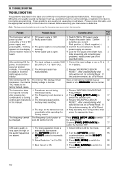
... incorrect control settings, or operator error due to the DC 2 appears on the data will be lost , do a Partial Reset. Problem Probable Cause Corrective Action Page Ref. Black: negative (-) pressing [ ]. After inspecting and correcting any problems, install a new fuse of the blown fuse. 2 heard. If display. after 2 Faulty power cable. 2 Inspect the power cable. After switching ON the transceiver, the internal TNC resets to 15.8 V DC). 16 V battery. memory need resetting. 4 The keys on...
... incorrect control settings, or operator error due to the DC 2 appears on the data will be lost , do a Partial Reset. Problem Probable Cause Corrective Action Page Ref. Black: negative (-) pressing [ ]. After inspecting and correcting any problems, install a new fuse of the blown fuse. 2 heard. If display. after 2 Faulty power cable. 2 Inspect the power cable. After switching ON the transceiver, the internal TNC resets to 15.8 V DC). 16 V battery. memory need resetting. 4 The keys on...

Operation Manual
Page 152
..., TX 30 Sidetone, Volume 30, 44 Transmission 30 Zero Beat, Auto 30 DCS Code ID Scan 36 Demonstration Mode 99 Digital Recording Unit (optional) Erasing a Recorded Message 90 Interval Time, Changing ......... 90 Playback 89 Playback Volume 90 Recording 89 Direct Frequency Entry 37 Display Brightness 75 Contrast 75 DRU-3A, Installation 97 DSP Auto Beat Cancel 56 Changing the Receive Filter Bandwidth 55 DSP Filters 55 Manual Beat Cancel 56 Noise...
..., TX 30 Sidetone, Volume 30, 44 Transmission 30 Zero Beat, Auto 30 DCS Code ID Scan 36 Demonstration Mode 99 Digital Recording Unit (optional) Erasing a Recorded Message 90 Interval Time, Changing ......... 90 Playback 89 Playback Volume 90 Recording 89 Direct Frequency Entry 37 Display Brightness 75 Contrast 75 DRU-3A, Installation 97 DSP Auto Beat Cancel 56 Changing the Receive Filter Bandwidth 55 DSP Filters 55 Manual Beat Cancel 56 Noise...


