Instruction Manual
Page 69
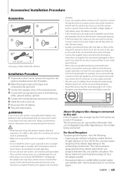
...; Do not use your own screws. battery. 2 Make the proper input and output wire connections for each unit. 3 Connect the speaker wires of the wiring harness. 4 Connect the wiring harness wires in the following : • Communicate with too much dust or the possibility of KDC-X994/ KDC-BT945U Installation Procedure 1 To prevent a short circuit, remove the key from the ignition...
...; Do not use your own screws. battery. 2 Make the proper input and output wire connections for each unit. 3 Connect the speaker wires of the wiring harness. 4 Connect the wiring harness wires in the following : • Communicate with too much dust or the possibility of KDC-X994/ KDC-BT945U Installation Procedure 1 To prevent a short circuit, remove the key from the ignition...
Instruction Manual
Page 70
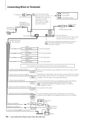
...- 70 | KDC-X994/ KDC-BT945U/ KDC-X794/ KDC-MP745U + Battery Depending on what antenna you are made, do not use the steering wheel remote control feature, you do not let the wire come out from ... REMOTE INPUT Car fuse box Ignition wire (Red) ACC Battery wire (Yellow) Ground wire (Black) · (To car chassis) To use the USB cable. To Kenwood disc changer/ External optional accessory &#... L Front output Sub Woofer output Antenna Cord FM/AM antenna input Fuse (10A) Wiring harness (Accessory1) White White/Black Gray Gray/Black Green Green/Black Purple Purple/Black AUX input...
...- 70 | KDC-X994/ KDC-BT945U/ KDC-X794/ KDC-MP745U + Battery Depending on what antenna you are made, do not use the steering wheel remote control feature, you do not let the wire come out from ... REMOTE INPUT Car fuse box Ignition wire (Red) ACC Battery wire (Yellow) Ground wire (Black) · (To car chassis) To use the USB cable. To Kenwood disc changer/ External optional accessory &#... L Front output Sub Woofer output Antenna Cord FM/AM antenna input Fuse (10A) Wiring harness (Accessory1) White White/Black Gray Gray/Black Green Green/Black Purple Purple/Black AUX input...

Quick Start Guide
Page 10
Accessories Before Installation 1 .....1 2 .....2 3 .....4 4 .....4 5(KDC-X994 / KDC-BT945Uonly) .....1 (9.5 ft) Installation Procedure 1. Reconnect the - If you could damage the unit. • If the power is not turned ON ("PROTECT" is displayed), the speaker wire may have a short-circuit or touched the chassis of the vehicle ...(ground), you use your own screws. Install the unit in the following order: ground, battery, ignition. 5. Connect the wiring harness wires in your car's ignition does not have been activated. battery. 8. To prevent a short circuit, remove the key from ...
Accessories Before Installation 1 .....1 2 .....2 3 .....4 4 .....4 5(KDC-X994 / KDC-BT945Uonly) .....1 (9.5 ft) Installation Procedure 1. Reconnect the - If you could damage the unit. • If the power is not turned ON ("PROTECT" is displayed), the speaker wire may have a short-circuit or touched the chassis of the vehicle ...(ground), you use your own screws. Install the unit in the following order: ground, battery, ignition. 5. Connect the wiring harness wires in your car's ignition does not have been activated. battery. 8. To prevent a short circuit, remove the key from ...

Quick Start Guide
Page 13
... to the control terminal of the film-type or short pole type antenna. Power control wire (Blue/White) P.CONT When using , connect either the telephone rings or during conversation. (KDC-X794/ KDC-MP745U only) ⁄ To connect the Kenwood navigation system, consult your car is stereo type and does not have any resistance. To... for the booster amplifier of the motor antenna, or to its power control terminal. Rear output RL Front output Sub Woofer output Fuse (10A) RL Wiring harness (Accessory1) FM/AM antenna input AUX input (Stereo) Use the mini-plug which is required.
... to the control terminal of the film-type or short pole type antenna. Power control wire (Blue/White) P.CONT When using , connect either the telephone rings or during conversation. (KDC-X794/ KDC-MP745U only) ⁄ To connect the Kenwood navigation system, consult your car is stereo type and does not have any resistance. To... for the booster amplifier of the motor antenna, or to its power control terminal. Rear output RL Front output Sub Woofer output Fuse (10A) RL Wiring harness (Accessory1) FM/AM antenna input AUX input (Stereo) Use the mini-plug which is required.


