
Quick Start Guide
Page 2
...Getting Started 3 Basic Operations 3 CD/USB/iPod 4 HD Radio™ Technology 4 Hands-free Phoning 5 Audio Adjustments/ Function Settings 6 Installation/ Connection 7 Wiring connection 8 Installing the Unit 9 Installing without using the USB device or iPod/ iPhone if it might hinder driving safety. • Make sure all important... may differ from the center of children and in this Guide, refer to the Instruction Manual on the following website: manual.kenwood.com/edition/im368 To refer to damage the connector. Dispose of recorded data. • Never put or leave any metallic ...
...Getting Started 3 Basic Operations 3 CD/USB/iPod 4 HD Radio™ Technology 4 Hands-free Phoning 5 Audio Adjustments/ Function Settings 6 Installation/ Connection 7 Wiring connection 8 Installing the Unit 9 Installing without using the USB device or iPod/ iPhone if it might hinder driving safety. • Make sure all important... may differ from the center of children and in this Guide, refer to the Instruction Manual on the following website: manual.kenwood.com/edition/im368 To refer to damage the connector. Dispose of recorded data. • Never put or leave any metallic ...

Quick Start Guide
Page 7
... • If your car's ignition key switch does not have been activated. CAUTION Install this unit during installation, consult your Kenwood dealer. • Reception may cause a short circuit, that can interfere with the cell-phone within the line-of-sight distance...not remove the caps on and off with the ignition key. Installation/ Connection Part list for installation: A Faceplate 1) B Trim plate 1) C Mounting sleeve 1) D Wiring harness 1) E Extraction key 2) F Flat head screw 4) G Round head screw 4) H Microphone (3 m 1) Basic procedure 1 Remove the key from the ignition ...
... • If your car's ignition key switch does not have been activated. CAUTION Install this unit during installation, consult your Kenwood dealer. • Reception may cause a short circuit, that can interfere with the cell-phone within the line-of-sight distance...not remove the caps on and off with the ignition key. Installation/ Connection Part list for installation: A Faceplate 1) B Trim plate 1) C Mounting sleeve 1) D Wiring harness 1) E Extraction key 2) F Flat head screw 4) G Round head screw 4) H Microphone (3 m 1) Basic procedure 1 Remove the key from the ignition ...
Quick Start Guide
Page 8
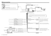
... car Light Blue/Yellow (Steering remote control wire) REMOTE CONT STEERING WHEEL REMOTE INPUT To use the steering wheel remote control feature, you need to the antenna control terminal in the vehicle. (Max. 300mA, 12V) To connect the Kenwood navigation MUTE system, consult your car is... stereo type and does not have any resistance. CONT (Not used) Blue ANT. Blue/White (Power control/ Antenna control wire) Brown (Mute control wire) Connect either to the power control P.CONT terminal ...
... car Light Blue/Yellow (Steering remote control wire) REMOTE CONT STEERING WHEEL REMOTE INPUT To use the steering wheel remote control feature, you need to the antenna control terminal in the vehicle. (Max. 300mA, 12V) To connect the Kenwood navigation MUTE system, consult your car is... stereo type and does not have any resistance. CONT (Not used) Blue ANT. Blue/White (Power control/ Antenna control wire) Brown (Mute control wire) Connect either to the power control P.CONT terminal ...
Quick Start Guide
Page 9
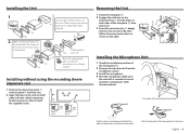
... the microphone to hold the mounting sleeve firmly in the unit (on both sides of your car Bend the appropriate tabs to the driver. Other wiring connection have been completed earlier. (page 8) 3 B 1 C D 2 Dashboard of the trim plate B, then pull it secured at several positions using ...the mounting sleeve (Japanese car) 1 Remove the mounting sleeve C and trim plate B from the H installation surface. 3 Install the microphone. 4 Wire the microphone cable up to fix on the place shown above. English | 9 Installing without using tape or other dirt from the unit. 2 Align ...
... the microphone to hold the mounting sleeve firmly in the unit (on both sides of your car Bend the appropriate tabs to the driver. Other wiring connection have been completed earlier. (page 8) 3 B 1 C D 2 Dashboard of the trim plate B, then pull it secured at several positions using ...the mounting sleeve (Japanese car) 1 Remove the mounting sleeve C and trim plate B from the H installation surface. 3 Install the microphone. 4 Wire the microphone cable up to fix on the place shown above. English | 9 Installing without using tape or other dirt from the unit. 2 Align ...


