
Instruction Manual
Page 30
... with a constant voltage supply, as with the ignition key. Installation/connection Part list: A Faceplate 1) B Escutcheon 1) C Mounting sleeve 1) D Wiring harness 1) E Removal tool 2) F Flat head screw (for Nissan cars 4) G Round head screw (for Toyota cars 4) H Microphone (3 m) (KDC-X695 only 1) Basic procedure 1 Remove the key from the ignition switch, then disconnect the · terminal of the...
... with a constant voltage supply, as with the ignition key. Installation/connection Part list: A Faceplate 1) B Escutcheon 1) C Mounting sleeve 1) D Wiring harness 1) E Removal tool 2) F Flat head screw (for Nissan cars 4) G Round head screw (for Toyota cars 4) H Microphone (3 m) (KDC-X695 only 1) Basic procedure 1 Remove the key from the ignition switch, then disconnect the · terminal of the...
Instruction Manual
Page 32
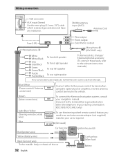
... To connect the Kenwood navigation system, consult your car is required. (Not used) Red (Ignition wire) Car fuse box ACC Ignition key switch Yellow (Battery wire) Black (Ground wire) To the metallic body or chassis of the car Car fuse box (Main fuse) - KDC-X395/ KDC-348U only) To use...Fuse (10A) Wiring harness D Rear output R L Front output Sub Woofer output Microphone H (KDC-X695 only) White White/Black Gray Gray/Black Green Green/Black Purple Purple/Black To front left speaker To front right speaker To rear left speaker To rear right speaker To Kenwood disc changer/ External...
... To connect the Kenwood navigation system, consult your car is required. (Not used) Red (Ignition wire) Car fuse box ACC Ignition key switch Yellow (Battery wire) Black (Ground wire) To the metallic body or chassis of the car Car fuse box (Main fuse) - KDC-X395/ KDC-348U only) To use...Fuse (10A) Wiring harness D Rear output R L Front output Sub Woofer output Microphone H (KDC-X695 only) White White/Black Gray Gray/Black Green Green/Black Purple Purple/Black To front left speaker To front right speaker To rear left speaker To rear right speaker To Kenwood disc changer/ External...

Instruction Manual
Page 33
... slots on each side, then follow the arrows instructions as shown on both sides of your car C 4 5 B Bend the appropriate tabs to the C unit. Other wiring connection has been completed earlier. (page 32) 2 1 B A 2 Before attaching, make sure the direction of the escutcheon is correct. (Wider hooks on the bottom side.) D 2 1 ... on both sides) with the vehicle mounting bracket and secure the unit with the supplied screws. T N NT T/N B 8 mm MAX. Installing the unit 1 3 Connect the wiring harness to hold the mounting sleeve firmly in the unit (on the right.
... slots on each side, then follow the arrows instructions as shown on both sides of your car C 4 5 B Bend the appropriate tabs to the C unit. Other wiring connection has been completed earlier. (page 32) 2 1 B A 2 Before attaching, make sure the direction of the escutcheon is correct. (Wider hooks on the bottom side.) D 2 1 ... on both sides) with the vehicle mounting bracket and secure the unit with the supplied screws. T N NT T/N B 8 mm MAX. Installing the unit 1 3 Connect the wiring harness to hold the mounting sleeve firmly in the unit (on the right.


