
Instruction Manual
Page 1
KAC-X20 TWO CHANNEL POWER AMPLIFIER 7 page 2-7 INSTRUCTION MANUAL AMPLIFICATEUR 2 CANAUX 7 page 8-13 MODE D'EMPLOI AMPLIFICADOR DE POTENCIA DE DOS CANALES 7 página 14-19 MANUAL DE INSTRUCCIONES Take the time to the model and serial numbers whenever you obtain the best performance from your Kenwood dealer for information or service on the warranty card, and in the space provided below. Model KAC-X20 Serial number US Residence Only Register...
KAC-X20 TWO CHANNEL POWER AMPLIFIER 7 page 2-7 INSTRUCTION MANUAL AMPLIFICATEUR 2 CANAUX 7 page 8-13 MODE D'EMPLOI AMPLIFICADOR DE POTENCIA DE DOS CANALES 7 página 14-19 MANUAL DE INSTRUCCIONES Take the time to the model and serial numbers whenever you obtain the best performance from your Kenwood dealer for information or service on the warranty card, and in the space provided below. Model KAC-X20 Serial number US Residence Only Register...
Instruction Manual
Page 2
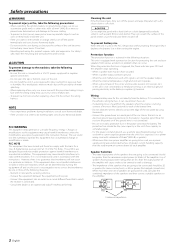
... speakers that are going to be connected should be working right, consult your unit to malfunction. • To prevent a short circuit when replacing a fuse, first disconnect the wiring harness. Use of speakers having input power ratings that can scratch the surface of the FCC Rules. Using a fuse with the wrong rating may cause your Kenwood dealer. The user could lose the authority to operate this unit directly from various accidents or problems...
... speakers that are going to be connected should be working right, consult your unit to malfunction. • To prevent a short circuit when replacing a fuse, first disconnect the wiring harness. Use of speakers having input power ratings that can scratch the surface of the FCC Rules. Using a fuse with the wrong rating may cause your Kenwood dealer. The user could lose the authority to operate this unit directly from various accidents or problems...
Instruction Manual
Page 3
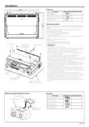
... Cooling fan Self-tapping screw (ø5 × 18 mm) Installation board, etc. (thickness : 15 mm or more) 272 mm 286 mm Installation procedure Since there are large variety of settings and connections possible according to applications, read the instruction manual well to the intended usage. 3.Connect the input and output wires of the units. 4.Connect the speaker wires. 5.Connect the power wire, power control wire and grounding wire following this unit in a location which...
... Cooling fan Self-tapping screw (ø5 × 18 mm) Installation board, etc. (thickness : 15 mm or more) 272 mm 286 mm Installation procedure Since there are large variety of settings and connections possible according to applications, read the instruction manual well to the intended usage. 3.Connect the input and output wires of the units. 4.Connect the speaker wires. 5.Connect the power wire, power control wire and grounding wire following this unit in a location which...
Instruction Manual
Page 4
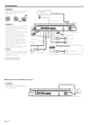
... nearby the battery's positive terminal. Battery Ground wire* * Commercially available parts Power control wire Left input Right input Lead terminal* Right speaker Left speaker ■ Bridged Connections Speaker (Bridged) ■ Remote cable connection (Optional accessory) 2CAUTION • Before connecting the remote controller cables, always turn the power off and check connections. • Be sure to turn the Bass boost level knob all the way to appropriate speaker connectors separately. FUSE(30As2) POWER IN Remote cable (6.0 m : 19.7 ft) Remote controller 4 English Do...
... nearby the battery's positive terminal. Battery Ground wire* * Commercially available parts Power control wire Left input Right input Lead terminal* Right speaker Left speaker ■ Bridged Connections Speaker (Bridged) ■ Remote cable connection (Optional accessory) 2CAUTION • Before connecting the remote controller cables, always turn the power off and check connections. • Be sure to turn the Bass boost level knob all the way to appropriate speaker connectors separately. FUSE(30As2) POWER IN Remote cable (6.0 m : 19.7 ft) Remote controller 4 English Do...
Instruction Manual
Page 5
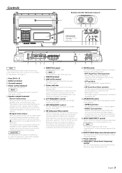
... the signal input from the line input terminal is output. 9 Power indicator When the power is 2Ω or greater for adjustment. (See page 3) 1 Fuse (30 A × 2) 2 Battery terminal 3 Ground terminal 4 Power control terminal Controls the unit ON/OFF. Check whether there is any indication of the amplifier. • STEREO position: The amplifier can be boosted. HPF FREQUENCY control Sets the cutoff frequency when the "FILTER" switch is set with this position and make bridged connections to select the operation mode of trouble. (See page 2) 0 LPF FREQUENCY control Sets the cutoff...
... the signal input from the line input terminal is output. 9 Power indicator When the power is 2Ω or greater for adjustment. (See page 3) 1 Fuse (30 A × 2) 2 Battery terminal 3 Ground terminal 4 Power control terminal Controls the unit ON/OFF. Check whether there is any indication of the amplifier. • STEREO position: The amplifier can be boosted. HPF FREQUENCY control Sets the cutoff frequency when the "FILTER" switch is set with this position and make bridged connections to select the operation mode of trouble. (See page 2) 0 LPF FREQUENCY control Sets the cutoff...
Instruction Manual
Page 6
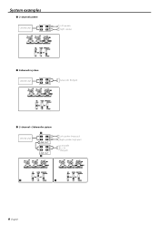
System examples ■ 2-channel system CENTER UNIT L L RR Left speaker Right speaker ■ Subwoofer system CENTER UNIT L L RR Subwoofer (Bridged) ■ 2-channel + Subwoofer system CENTER UNIT f L L RR LINE OUT L L RR LINE OUT g Left speaker (High pass) Right speaker (High pass) Subwoofer (L + R) (Bridged) f g 6 English
System examples ■ 2-channel system CENTER UNIT L L RR Left speaker Right speaker ■ Subwoofer system CENTER UNIT L L RR Subwoofer (Bridged) ■ 2-channel + Subwoofer system CENTER UNIT f L L RR LINE OUT L L RR LINE OUT g Left speaker (High pass) Right speaker (High pass) Subwoofer (L + R) (Bridged) f g 6 English
Instruction Manual
Page 7
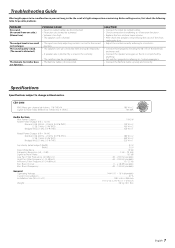
....) (Blown fuse.) The output level is distorted.) The Remote Controller does not function. SOLUTION • Connect the input (or output) cables. • Check connections by referring to . • Replace the fuse and use lower volume. • After check the speaker cord and fixing the cause of the short, replace the fuse. • Adjust the control correctly referring to change without notice. Specifications Specifications subject to . • Connect them properly checking the + / - The sound quality is bad. (The sound...
....) (Blown fuse.) The output level is distorted.) The Remote Controller does not function. SOLUTION • Connect the input (or output) cables. • Check connections by referring to . • Replace the fuse and use lower volume. • After check the speaker cord and fixing the cause of the short, replace the fuse. • Adjust the control correctly referring to change without notice. Specifications Specifications subject to . • Connect them properly checking the + / - The sound quality is bad. (The sound...


