
Instruction Manual
Page 1
... below. Model KAC-8404 Serial number US Residence Only Register Online Register your new power amplifier. Familiarity with installation and operation procedures will help you call upon your Kenwood dealer for information or service on the warranty card, and in the spaces designated on the product. Refer to read through this instruction manual. KAC-8404 4/3/2 CHANNEL POWER AMPLIFIER 7 page 2-5 INSTRUCTION MANUAL AMPLIFICATEUR DE PUISSANCE 4/3/2 CANAUX 7 page 6-9 MODE D'EMPLOI AMPLIFICADOR DE POTENCIA...
... below. Model KAC-8404 Serial number US Residence Only Register Online Register your new power amplifier. Familiarity with installation and operation procedures will help you call upon your Kenwood dealer for information or service on the warranty card, and in the spaces designated on the product. Refer to read through this instruction manual. KAC-8404 4/3/2 CHANNEL POWER AMPLIFIER 7 page 2-5 INSTRUCTION MANUAL AMPLIFICATEUR DE PUISSANCE 4/3/2 CANAUX 7 page 6-9 MODE D'EMPLOI AMPLIFICADOR DE POTENCIA...
Instruction Manual
Page 2
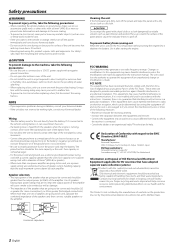
... direct sunlight or excessive heat or humidity. Wiring • Take the battery wire for a Class B digital device, pursuant to malfunction. • To prevent a short circuit when replacing a fuse, first disconnect the wiring harness. Use of speakers having input power ratings that are going to be working right, consult your Kenwood dealer. • If the unit does not seem to be used , calculate the combined impedance of the speakers and then connect suitable speakers...
... direct sunlight or excessive heat or humidity. Wiring • Take the battery wire for a Class B digital device, pursuant to malfunction. • To prevent a short circuit when replacing a fuse, first disconnect the wiring harness. Use of speakers having input power ratings that are going to be working right, consult your Kenwood dealer. • If the unit does not seem to be used , calculate the combined impedance of the speakers and then connect suitable speakers...
Instruction Manual
Page 3
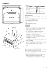
... - terminal of the battery to prevent short circuits. 2.Set the unit according to the intended usage. 3.Connect the input and output wires of the units. 4.Connect the speaker wires. 5.Connect the power wire, power control wire and grounding wire following situations: This unit is activated in the following this unit in a location which it . • This unit has cooling fan to the speaker output. • When the internal temperature is high and unit won't operate. • When a ground wire of...
... - terminal of the battery to prevent short circuits. 2.Set the unit according to the intended usage. 3.Connect the input and output wires of the units. 4.Connect the speaker wires. 5.Connect the power wire, power control wire and grounding wire following situations: This unit is activated in the following this unit in a location which it . • This unit has cooling fan to the speaker output. • When the internal temperature is high and unit won't operate. • When a ground wire of...
Instruction Manual
Page 4
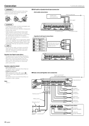
... (No line output center unit etc.) Speaker output terminals • Stereo Connections: The speakers to be connected should have a maximum power output of no unconnected wires or connectors are touching the car body. Fuse 40 A × 1 ■ Power wire and Speaker wire connection Power control wire* (RCA cable connection) B channel input Lead terminal* Terminal cover Battery wire* Protective Fuse* Battery Ground wire* • Stereo Connections B channel Right speaker B channel Left speaker A channel Right speaker A channel Left speaker • Bridged Connections B channel Speaker...
... (No line output center unit etc.) Speaker output terminals • Stereo Connections: The speakers to be connected should have a maximum power output of no unconnected wires or connectors are touching the car body. Fuse 40 A × 1 ■ Power wire and Speaker wire connection Power control wire* (RCA cable connection) B channel input Lead terminal* Terminal cover Battery wire* Protective Fuse* Battery Ground wire* • Stereo Connections B channel Right speaker B channel Left speaker A channel Right speaker A channel Left speaker • Bridged Connections B channel Speaker...
Instruction Manual
Page 5
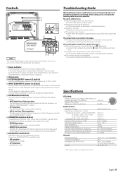
... 9 / · of the terminals and wires well. ✔ A speaker wire is pinched by a screw in your unit may be the result of the short, replace the fuse. The output level is too small (or too large). ✔ The input sensitivity adjusting control is turned on the right as a high-power monaural amplifier. 7 BASS BOOST switch (B.ch) Setting this position and make bridged connections to be a malfunction in the car body. ☞ Connect the speaker wire again so that...
... 9 / · of the terminals and wires well. ✔ A speaker wire is pinched by a screw in your unit may be the result of the short, replace the fuse. The output level is too small (or too large). ✔ The input sensitivity adjusting control is turned on the right as a high-power monaural amplifier. 7 BASS BOOST switch (B.ch) Setting this position and make bridged connections to be a malfunction in the car body. ☞ Connect the speaker wire again so that...


