
Operation Manual
Page 3
... our amps in many don't participate) a baseline when comparing amplifiers of similar power output. Before You Begin We need the original dated receipt. In addition, loud music may hinder your Jensen purchase decision was a sound one, and remember "If it ," is power - Introduction The Jensen Power series of the way, so please keep reading. Afterwards, you...
... our amps in many don't participate) a baseline when comparing amplifiers of similar power output. Before You Begin We need the original dated receipt. In addition, loud music may hinder your Jensen purchase decision was a sound one, and remember "If it ," is power - Introduction The Jensen Power series of the way, so please keep reading. Afterwards, you...
Operation Manual
Page 4
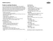
...8226; Stereo / Mono Mode Switch (Power 400.2 only) • 2/ 3 / 4 Channel Mode Switch (Power 760.4 only) Power 900.1 • Mono Subwoofer Amp • Low Pass Filter 40 - 240 Hz (Power 900.1) • Subsonic Filter 10 - 40 Hz, 12dB / octave (Power 900.1) • Remote Input Level Control... DC-offset and Thermal Overload Protection Circuitry • Diagnostic LED's - POWER Amplifiers Features and Specifications Your new Jensen Power mobile stereo power amplifier is the amplifier of choice for the high demands of amplifiers takes Mobile Hi-Fi to new heights. With its deep-bass reproduction...
...8226; Stereo / Mono Mode Switch (Power 400.2 only) • 2/ 3 / 4 Channel Mode Switch (Power 760.4 only) Power 900.1 • Mono Subwoofer Amp • Low Pass Filter 40 - 240 Hz (Power 900.1) • Subsonic Filter 10 - 40 Hz, 12dB / octave (Power 900.1) • Remote Input Level Control... DC-offset and Thermal Overload Protection Circuitry • Diagnostic LED's - POWER Amplifiers Features and Specifications Your new Jensen Power mobile stereo power amplifier is the amplifier of choice for the high demands of amplifiers takes Mobile Hi-Fi to new heights. With its deep-bass reproduction...
Operation Manual
Page 5
... the electrical system. right and twice! do things - Attempting to . Supplies and Tools Needed To install the amplifier, you will not damage any time. When selecting a location, remember that your Jensen Power series amp will not operate properly and could become permanently damaged. Common mounting locations include under the front passenger seat or...
... the electrical system. right and twice! do things - Attempting to . Supplies and Tools Needed To install the amplifier, you will not damage any time. When selecting a location, remember that your Jensen Power series amp will not operate properly and could become permanently damaged. Common mounting locations include under the front passenger seat or...
Operation Manual
Page 6
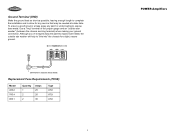
... as a guide when installing your amplifier(s): MODEL NUMBER 400.2 760.4 900.1 MAX CURRENT DRAW 25A 40A 60A MIN WIRE GAUGE #8 #8 #6 Power Terminal (+12V/B+) Connect the main power wire to the battery, within 18 inches from the receiver to the amplifier remote terminal. Remote Terminal (REM) Connect the power antenna or amplifier turn-on lead from the positive...
... as a guide when installing your amplifier(s): MODEL NUMBER 400.2 760.4 900.1 MAX CURRENT DRAW 25A 40A 60A MIN WIRE GAUGE #8 #8 #6 Power Terminal (+12V/B+) Connect the main power wire to the battery, within 18 inches from the receiver to the amplifier remote terminal. Remote Terminal (REM) Connect the power antenna or amplifier turn-on lead from the positive...
Operation Manual
Page 7
...length to complete the installation and to allow for any paint or undercoating to "bite into" the chassis for a tight, secure ground. POWER INPUT GND REM +12V Drill hole in chassis sheet metal. Although you've scraped away the paint to expose bare metal, the outside ...washer" (between the chassis and ring terminal) when making your ground connection. Replacement Fuse Requirements (FUSE) Model 400.2 760.4 900.1 Quantity 1 2 2 Amps 25 20 30 Type ATO ATO ATO 5 POWER Amplifiers Use a "ring" terminal of the proper gauge and an "outside star washer will help to expose bare metal...
...length to complete the installation and to allow for any paint or undercoating to "bite into" the chassis for a tight, secure ground. POWER INPUT GND REM +12V Drill hole in chassis sheet metal. Although you've scraped away the paint to expose bare metal, the outside ...washer" (between the chassis and ring terminal) when making your ground connection. Replacement Fuse Requirements (FUSE) Model 400.2 760.4 900.1 Quantity 1 2 2 Amps 25 20 30 Type ATO ATO ATO 5 POWER Amplifiers Use a "ring" terminal of the proper gauge and an "outside star washer will help to expose bare metal...
Operation Manual
Page 8
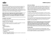
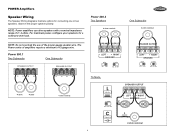
... Subwoofer One Subwoofer SPEAKER OUTPUT SPEAKER OUTPUT Power 400.2 Two Speakers 4 ohm nominal SPEAKER OUTPUT + LEFT - + RIGHT BRIDGED MODE MONO STEREO X-OVER FULL LPF HPF One Subwoofer 4 ohm nominal SPEAKER... nominal 6 Observe the proper speaker polarity. NOTE: Power amplifiers can drive speakers with a nominal impedance range of 2~ 4-ohms. For maximum power, configure your speakers for connecting one or two speakers. The Power series of amplifiers require a minimum of the proper gauge speaker wire. POWER Amplifiers Speaker Wiring The Speaker Wiring diagrams illustrate options for...
... Subwoofer One Subwoofer SPEAKER OUTPUT SPEAKER OUTPUT Power 400.2 Two Speakers 4 ohm nominal SPEAKER OUTPUT + LEFT - + RIGHT BRIDGED MODE MONO STEREO X-OVER FULL LPF HPF One Subwoofer 4 ohm nominal SPEAKER... nominal 6 Observe the proper speaker polarity. NOTE: Power amplifiers can drive speakers with a nominal impedance range of 2~ 4-ohms. For maximum power, configure your speakers for connecting one or two speakers. The Power series of amplifiers require a minimum of the proper gauge speaker wire. POWER Amplifiers Speaker Wiring The Speaker Wiring diagrams illustrate options for...
Operation Manual
Page 9
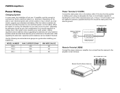
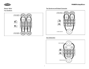
Power 760.4 Four Speakers 4 ohm nominal 2 ohm minimum X-OVER FULL LPF HPF + CH1 + CH3 - + CH2 + CH4 - FULL LPF HPF + BRIDGED - 4 ohm nominal Two Subwoofers 4 ohm nominal X-OVER FULL LPF HPF + CH1 + CH3 - + CH2 + CH4 - FULL LPF HPF + BRIDGED - 4 ohm nominal 7 FULL LPF HPF + BRIDGED - 4 ohm nominal 2 ohm minimum Two Speakers and Bridged Subwoofer POWER Amplifiers 4 ohm nominal 2 ohm minimum X-OVER FULL LPF HPF + CH1 + CH3 - + CH2 + CH4 -
Power 760.4 Four Speakers 4 ohm nominal 2 ohm minimum X-OVER FULL LPF HPF + CH1 + CH3 - + CH2 + CH4 - FULL LPF HPF + BRIDGED - 4 ohm nominal Two Subwoofers 4 ohm nominal X-OVER FULL LPF HPF + CH1 + CH3 - + CH2 + CH4 - FULL LPF HPF + BRIDGED - 4 ohm nominal 7 FULL LPF HPF + BRIDGED - 4 ohm nominal 2 ohm minimum Two Speakers and Bridged Subwoofer POWER Amplifiers 4 ohm nominal 2 ohm minimum X-OVER FULL LPF HPF + CH1 + CH3 - + CH2 + CH4 -
Operation Manual
Page 10
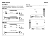
...-seat mounting will require a 6-12 foot RCA cable. Power 400.2 Input Wiring - Stereo Mode RCA Cable Input Wiring - Connect an RCA cable from your receiver to the RCA input on your amplifier. Mono Mode CAR STEREO / SOURCE UNIT CAR STEREO / SOURCE UNIT Power 760.4 The Power 760.4 can be configured for three different input modes... HPF 12dB 40Hz 300Hz 40Hz 300Hz X-OVER 234 min max 0dB 12dB 40Hz 300Hz 40Hz 300Hz FULL LPF HPF LINE OUTPUT 8 Mono Mode RCA Cable Power 900.1 Input Wiring -
...-seat mounting will require a 6-12 foot RCA cable. Power 400.2 Input Wiring - Stereo Mode RCA Cable Input Wiring - Connect an RCA cable from your receiver to the RCA input on your amplifier. Mono Mode CAR STEREO / SOURCE UNIT CAR STEREO / SOURCE UNIT Power 760.4 The Power 760.4 can be configured for three different input modes... HPF 12dB 40Hz 300Hz 40Hz 300Hz X-OVER 234 min max 0dB 12dB 40Hz 300Hz 40Hz 300Hz FULL LPF HPF LINE OUTPUT 8 Mono Mode RCA Cable Power 900.1 Input Wiring -
Operation Manual
Page 11
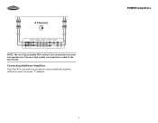
4 Channel MODE 234 CH2 CH4 CH1 CH3 LINE INPUT LEVEL BASS EQ HPF LPF X-OVER MODE FULL LPF HPF min max 0dB 12dB 40Hz 300Hz 40Hz 300Hz X-OVER 234 min max 0dB 12dB 40Hz 300Hz 40Hz 300Hz FULL LPF HPF LINE OUTPUT NOTE: The use of good quality RCA cables is just as important as power and speaker wire. Connecting Additional Amplifiers Pass-Thru RCA connectors are provided to connect additional amplifiers without the need to purchase "Y" adapters. 9 POWER Amplifiers Choose a high quality low capacitance cable for the best results.
4 Channel MODE 234 CH2 CH4 CH1 CH3 LINE INPUT LEVEL BASS EQ HPF LPF X-OVER MODE FULL LPF HPF min max 0dB 12dB 40Hz 300Hz 40Hz 300Hz X-OVER 234 min max 0dB 12dB 40Hz 300Hz 40Hz 300Hz FULL LPF HPF LINE OUTPUT NOTE: The use of good quality RCA cables is just as important as power and speaker wire. Connecting Additional Amplifiers Pass-Thru RCA connectors are provided to connect additional amplifiers without the need to purchase "Y" adapters. 9 POWER Amplifiers Choose a high quality low capacitance cable for the best results.
Operation Manual
Page 12
...The high pass filter will be able to a higher setting (80-100Hz). Mode Switch Power 400.2 The 400.2 comes equiped with certain enclosure/subwoofer combinations that the amplifier is in your subwoofer/enclosure combination. Now your subwoofers at 40Hz, which would normally listen.... Other uses might include limiting the low frequencies to smaller speakers (6 1/2", 6 X 9", etc.) by ear. Crossover (X-OVER) The Jensen Power series of amplifiers have a 2-channel input from your vehicle, with a 2/3/4 MODE switch and can be useful with a MONO/STEREO MODE switch. Select LPF...
...The high pass filter will be able to a higher setting (80-100Hz). Mode Switch Power 400.2 The 400.2 comes equiped with certain enclosure/subwoofer combinations that the amplifier is in your subwoofer/enclosure combination. Now your subwoofers at 40Hz, which would normally listen.... Other uses might include limiting the low frequencies to smaller speakers (6 1/2", 6 X 9", etc.) by ear. Crossover (X-OVER) The Jensen Power series of amplifiers have a 2-channel input from your vehicle, with a 2/3/4 MODE switch and can be useful with a MONO/STEREO MODE switch. Select LPF...
Operation Manual
Page 13
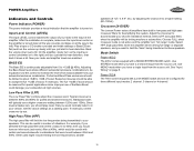
... is complete, reconnect the battery negative terminal. The amplifier power light should operate. All speakers should come on the receiver, but do not turn up the receiver volume slightly. POWER Amplifiers Remote Input Level Control The Power 900.1 comes equipped with a Remote Input Level Control.... Simply plug the 6-pin modular cable into the amplifier and then into the Remote Input Level Control to be disconnected. Power Min Max REMOTE CONTROL POWER PROTECT REMOTE CONTROL BASS BOOST SUB SONIC LOW PASS LEVEL OUTPUT INPUT L L...
... is complete, reconnect the battery negative terminal. The amplifier power light should operate. All speakers should come on the receiver, but do not turn up the receiver volume slightly. POWER Amplifiers Remote Input Level Control The Power 900.1 comes equipped with a Remote Input Level Control.... Simply plug the 6-pin modular cable into the amplifier and then into the Remote Input Level Control to be disconnected. Power Min Max REMOTE CONTROL POWER PROTECT REMOTE CONTROL BASS BOOST SUB SONIC LOW PASS LEVEL OUTPUT INPUT L L...
Operation Manual
Page 14
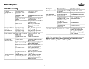
... Check speaker connections Verify that speakers are connected properly Check speakers Check crossovers Check speaker polarity; POWER Amplifiers Troubleshooting Problem Amplifier does not turn on amp set too high Amplifier driving 2 ohm load for long durations Corrective Action Check fuse(s) Check head unit fuse(s) and... wiring Replace fuse and identify cause of failure Replace fuse and identify cause of phase Check all the power connections are connected to the amplifier. reverse the connection to one speaker only if two subwoofers are correct, this would indicate an internal problem...
... Check speaker connections Verify that speakers are connected properly Check speakers Check crossovers Check speaker polarity; POWER Amplifiers Troubleshooting Problem Amplifier does not turn on amp set too high Amplifier driving 2 ohm load for long durations Corrective Action Check fuse(s) Check head unit fuse(s) and... wiring Replace fuse and identify cause of failure Replace fuse and identify cause of phase Check all the power connections are connected to the amplifier. reverse the connection to one speaker only if two subwoofers are correct, this would indicate an internal problem...
Operation Manual
Page 15
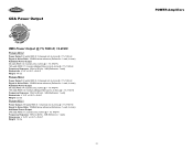
...Power Output RMS Power Output @ 1% THD+N, 14.4VDC Power 400.2 Power Output: 60 watts RMS X 2 channels into 4-ohms @ < 1% THD+N Signal to Noise Ratio: 100dBA below reference (Reference: 1 watt, 4-ohms) Additional Power...Weight: 4.4 lbs Power 760.4 Power Output: 60 watts RMS X 4 channels into 4-ohms @ < 1% THD+N Signal to Noise Ratio: 100dBA below reference (Reference: 1 watt, 4-ohms) Additional Power Output: 80 ...6.2 lbs Power 900.1 Power Output: 230 watts RMS X 1 channels into 4-ohms @ < 1% THD+N Signal to Noise Ratio: 100dBA below reference (Reference: 1 watt, 4-ohms) Additional Power Output: 340...
...Power Output RMS Power Output @ 1% THD+N, 14.4VDC Power 400.2 Power Output: 60 watts RMS X 2 channels into 4-ohms @ < 1% THD+N Signal to Noise Ratio: 100dBA below reference (Reference: 1 watt, 4-ohms) Additional Power...Weight: 4.4 lbs Power 760.4 Power Output: 60 watts RMS X 4 channels into 4-ohms @ < 1% THD+N Signal to Noise Ratio: 100dBA below reference (Reference: 1 watt, 4-ohms) Additional Power Output: 80 ...6.2 lbs Power 900.1 Power Output: 230 watts RMS X 1 channels into 4-ohms @ < 1% THD+N Signal to Noise Ratio: 100dBA below reference (Reference: 1 watt, 4-ohms) Additional Power Output: 340...

Operation Manual
Page 16
POWER Amplifiers 14
POWER Amplifiers 14