KY-F75U 52 page instruction manual (3MB)
Page 1
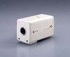
KY-F75 Serial No. which is made from 100% recycled paper. Retain this information for future reference. This instruction book is located on the unit. Model No. LWT0059-001A For Customer Use: Enter below the Serial No. Introduction Preparations 3CCD Digital Camera 3CCD Digitale Kamera 3CCD Caméra numérique KY-F75 INSTRUCTIONS BEDIENUNGSANLEITUNG MANUEL D'INSTRUCTIONS Recording Settings Others Illustration with optional lens attachment.
KY-F75 Serial No. which is made from 100% recycled paper. Retain this information for future reference. This instruction book is located on the unit. Model No. LWT0059-001A For Customer Use: Enter below the Serial No. Introduction Preparations 3CCD Digital Camera 3CCD Digitale Kamera 3CCD Caméra numérique KY-F75 INSTRUCTIONS BEDIENUNGSANLEITUNG MANUEL D'INSTRUCTIONS Recording Settings Others Illustration with optional lens attachment.
KY-F75U 52 page instruction manual (3MB)
Page 6
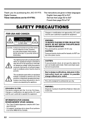
... English from page E2 to E47 German from page G2 to G47 French from page F2 to operate the equipment. Information for KY-F75U. NO USER SERVICEABLE PARTS INSIDE. These instructions are subject to persons. CAUTION: To prevent electric shocks and fire hazards, do ... accompanying the appliance. Refer servicing to the presence of uninsulated "dangerous voltage" within an equilateral triangle is designed for purchasing the JVC KY-F75 Digital Camera. REFER SERVICING TO QUALIFIED SERVICE PERSONNEL. The lightning flash with Canadian ICES-003. • Cet appareil numérique de ...
... English from page E2 to E47 German from page G2 to G47 French from page F2 to operate the equipment. Information for KY-F75U. NO USER SERVICEABLE PARTS INSIDE. These instructions are subject to persons. CAUTION: To prevent electric shocks and fire hazards, do ... accompanying the appliance. Refer servicing to the presence of uninsulated "dangerous voltage" within an equilateral triangle is designed for purchasing the JVC KY-F75 Digital Camera. REFER SERVICING TO QUALIFIED SERVICE PERSONNEL. The lightning flash with Canadian ICES-003. • Cet appareil numérique de ...
KY-F75U 52 page instruction manual (3MB)
Page 8
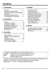
Preparations System 10 Preparing the computer 12 Connection to record 20 Starting the [KY-LINK] application software 21 Freezing the image 22 Capturing the still image on the computer (Capture 23 Characters and symbols used in these instructions are not used in these companies.... and EEI operations 45 Specifications 46 How to computer 14 Mounting and setting the lens 15 Connecting the AC adapter 16 Mounting the camera 18 Fall prevention 19 3. Contents 1. Settings Features 5 Accessories and attachments 5 Cautionary notes for the correct usage of this instruction ...
Preparations System 10 Preparing the computer 12 Connection to record 20 Starting the [KY-LINK] application software 21 Freezing the image 22 Capturing the still image on the computer (Capture 23 Characters and symbols used in these instructions are not used in these companies.... and EEI operations 45 Specifications 46 How to computer 14 Mounting and setting the lens 15 Connecting the AC adapter 16 Mounting the camera 18 Fall prevention 19 3. Contents 1. Settings Features 5 Accessories and attachments 5 Cautionary notes for the correct usage of this instruction ...
KY-F75U 52 page instruction manual (3MB)
Page 9
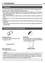
...camera and allow the camera image to replacement of the optical filter.) Accessories and attachments Clamp filter (2 pcs.) For IEEE1394 cable and DC power cable ( ੬ page E14, E16) CD-ROM (1) Exclusive application software [KY...215; 1024-pixel digital video signal possible. ● Built-in the computer. 1. Introduction Features ● The KY-F75 is a digital camera employing three 1/2" CCD with regards to...The exclusive application software [KY-LINK] is output as the IEEE1394 host adapter. Use the separately sold ). (Please consult the nearest JVC Service Center or your ...
...camera and allow the camera image to replacement of the optical filter.) Accessories and attachments Clamp filter (2 pcs.) For IEEE1394 cable and DC power cable ( ੬ page E14, E16) CD-ROM (1) Exclusive application software [KY...215; 1024-pixel digital video signal possible. ● Built-in the computer. 1. Introduction Features ● The KY-F75 is a digital camera employing three 1/2" CCD with regards to...The exclusive application software [KY-LINK] is output as the IEEE1394 host adapter. Use the separately sold ). (Please consult the nearest JVC Service Center or your ...

KY-F75U 52 page instruction manual (3MB)
Page 11
...use the attached screws. E7 Mounting and setting the lens ( ੬ page E15) · Camera mounting bracket Although the mounting bracket is mounted on the bottom of the camera when shipped, the bracket can be mounted on the lenses that exceed 6mm may result in malfunction of... the camera. Mounting the camera ( ੬ page E18) » Locking screws for the camera mounting bracket (M2.6 × 6mm, 3 units) ¿ Screw holes for mounting the camera (1/4-inch) Used when mounting the camera to the type C mount lens, there are restrictions...
...use the attached screws. E7 Mounting and setting the lens ( ੬ page E15) · Camera mounting bracket Although the mounting bracket is mounted on the bottom of the camera when shipped, the bracket can be mounted on the lenses that exceed 6mm may result in malfunction of... the camera. Mounting the camera ( ੬ page E18) » Locking screws for the camera mounting bracket (M2.6 × 6mm, 3 units) ¿ Screw holes for mounting the camera (1/4-inch) Used when mounting the camera to the type C mount lens, there are restrictions...
KY-F75U 52 page instruction manual (3MB)
Page 12
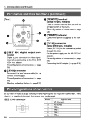
... through this inlet. If the direction of connectors ( ੬ page E8) ᕦ [LENS] connector To connect the lens' camera cable (for video signal. 1. Pin configurations of connectors Be sure to connect external devices such as a trigger switch or flash unit...DC 12V) for the camera is incorrect, the camera may be damaged. TPA + Introduction (continued) Part names and their functions (continued) [Rear] ᕦ ᕧ ᕨ REMOTE LENS IEEE1394 DC IN POWER SEE INSTRUCTION MANUAL ᕥ ᕩ ᕥ [IEEE1394] digital output connector Digital output connector for iris...
... through this inlet. If the direction of connectors ( ੬ page E8) ᕦ [LENS] connector To connect the lens' camera cable (for video signal. 1. Pin configurations of connectors Be sure to connect external devices such as a trigger switch or flash unit...DC 12V) for the camera is incorrect, the camera may be damaged. TPA + Introduction (continued) Part names and their functions (continued) [Rear] ᕦ ᕧ ᕨ REMOTE LENS IEEE1394 DC IN POWER SEE INSTRUCTION MANUAL ᕥ ᕩ ᕥ [IEEE1394] digital output connector Digital output connector for iris...
KY-F75U 52 page instruction manual (3MB)
Page 14
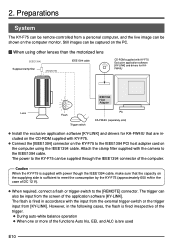
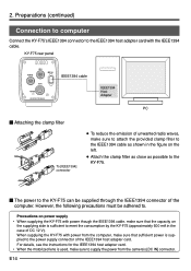
...or trigger-switch to the [REMOTE] connector. Still images can be captured on the PC. Ⅵ When using other lenses than the motorized lens [IEEE1394] Supplied clamp filter [REMOTE] IEEE1394 cable CD-ROM supplied with KY-F75: Exclusive application software [KY-LINK] and drivers for KAFW4IU IEEE1394 Host Adapter Lens... to the IEEE1394 PCI host adapter card on the supplying side is fired in accordance with the camera to meet the consumption by the KY-F75 (approximately 600 mA in the following cases, the flash is fired irrespective of the trigger. ● During auto-white balance ...
...or trigger-switch to the [REMOTE] connector. Still images can be captured on the PC. Ⅵ When using other lenses than the motorized lens [IEEE1394] Supplied clamp filter [REMOTE] IEEE1394 cable CD-ROM supplied with KY-F75: Exclusive application software [KY-LINK] and drivers for KAFW4IU IEEE1394 Host Adapter Lens... to the IEEE1394 PCI host adapter card on the supplying side is fired in accordance with the camera to meet the consumption by the KY-F75 (approximately 600 mA in the following cases, the flash is fired irrespective of the trigger. ● During auto-white balance ...
KY-F75U 52 page instruction manual (3MB)
Page 15
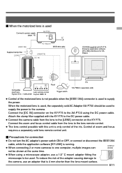
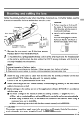
... the iris. Connect the [DC IN] connector on the KY-F75 to the [LENS] connector on the KY-F75. Attach the clamp filter supplied with the KY-F75 to the DC power cable. ● Connect the camera cable from the lens to the camera, use a 1/2" C-mount adapter fitting the microscope to be...the AC adapter's power switch ON or OFF, or connect or disconnect the IEEE1394 cable, while the application software [KY-LINK] is running. ● When connecting 2 or more cameras to one computer, multiple images can- 4 mm or shorter not be shown at the same time. ● When using the DC power ...
... the iris. Connect the [DC IN] connector on the KY-F75 to the [LENS] connector on the KY-F75. Attach the clamp filter supplied with the KY-F75 to the DC power cable. ● Connect the camera cable from the lens to the camera, use a 1/2" C-mount adapter fitting the microscope to be...the AC adapter's power switch ON or OFF, or connect or disconnect the IEEE1394 cable, while the application software [KY-LINK] is running. ● When connecting 2 or more cameras to one computer, multiple images can- 4 mm or shorter not be shown at the same time. ● When using the DC power ...
KY-F75U 52 page instruction manual (3MB)
Page 16
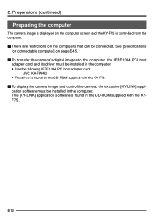
...on page E45. Ⅵ To transfer the camera's digital images to the computer, the IEEE1394 PCI host adapter card and its driver must be connected. Preparations (continued) Preparing the computer The camera image is displayed on the computer screen and the KY-F75 is controlled from the computer. Ⅵ... restrictions on the CD-ROM supplied with the KY-F75. Ⅵ To display the camera image and control the camera, the exclusive [KY-LINK] application software must be installed in the computer. ● Use the following IEEE1394 PCI host adapter card: JVC: KA-FW4IU ● The driver is found...
...on page E45. Ⅵ To transfer the camera's digital images to the computer, the IEEE1394 PCI host adapter card and its driver must be connected. Preparations (continued) Preparing the computer The camera image is displayed on the computer screen and the KY-F75 is controlled from the computer. Ⅵ... restrictions on the CD-ROM supplied with the KY-F75. Ⅵ To display the camera image and control the camera, the exclusive [KY-LINK] application software must be installed in the computer. ● Use the following IEEE1394 PCI host adapter card: JVC: KA-FW4IU ● The driver is found...
KY-F75U 52 page instruction manual (3MB)
Page 18
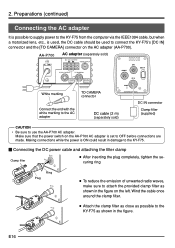
... is used, make sure to attach the provided clamp filter to the IEEE1394 host adapter card with power from the camera's [DC IN] connector. Precautions on power supply • When supplying the KY-F75 with power though the IEEE1394 cable, make sure that the capacity on the supplying side is supplied to... unwanted radio waves, make sure to supply the power from the computer, make sure that sufficient power is sufficient to meet the consumption by the KY-F75 (approximately 600 mA in the figure on the left. ● Attach the clamp filter as close as shown in the case of the ...
... is used, make sure to attach the provided clamp filter to the IEEE1394 host adapter card with power from the camera's [DC IN] connector. Precautions on power supply • When supplying the KY-F75 with power though the IEEE1394 cable, make sure that the capacity on the supplying side is supplied to... unwanted radio waves, make sure to supply the power from the computer, make sure that sufficient power is sufficient to meet the consumption by the KY-F75 (approximately 600 mA in the figure on the left. ● Attach the clamp filter as close as shown in the case of the ...
KY-F75U 52 page instruction manual (3MB)
Page 19
.... ባ Slowly turn ) as iris control is securely locked. Control of the iris is performed from the front of the camera, and then turn the lens unit or the KY-F75 slowly clockwise until it is performed automatically. ● When using a motorized lens, set to MANUAL. Mounting with the power... control the lens to be used lens. Ⅵ Iris mode settings on the setting screen of the application software [KY-LINK] in damage. ● Lens is securely threaded onto the camera. Insert the plug of the motorized lens is not possible when power is 4mm or less. 4 mm or shorter ...
.... ባ Slowly turn ) as iris control is securely locked. Control of the iris is performed from the front of the camera, and then turn the lens unit or the KY-F75 slowly clockwise until it is performed automatically. ● When using a motorized lens, set to MANUAL. Mounting with the power... control the lens to be used lens. Ⅵ Iris mode settings on the setting screen of the application software [KY-LINK] in damage. ● Lens is securely threaded onto the camera. Insert the plug of the motorized lens is not possible when power is 4mm or less. 4 mm or shorter ...
KY-F75U 52 page instruction manual (3MB)
Page 20
...cable (2 m) (separately sold) SEE INSTRUCTION MANUAL DC IN connector Clamp filter (supplied) CAUTION • Be sure to connect the KY-F75's [DC IN] connector and the [TO CAMERA] connector on the left. Making connections while the power is set to attach the provided clamp filter as shown in damage to ...the KY-F75. Ⅵ Connecting the DC power cable and attaching the filter clamp Clamp filter DC IN POWER ● ...
...cable (2 m) (separately sold) SEE INSTRUCTION MANUAL DC IN connector Clamp filter (supplied) CAUTION • Be sure to connect the KY-F75's [DC IN] connector and the [TO CAMERA] connector on the left. Making connections while the power is set to attach the provided clamp filter as shown in damage to ...the KY-F75. Ⅵ Connecting the DC power cable and attaching the filter clamp Clamp filter DC IN POWER ● ...

KY-F75U 52 page instruction manual (3MB)
Page 22
... unit, simply remove the 3 locking screws holding the camera mounting bracket. Preparations (continued) Mounting the camera < Mounting method > Rotation prevention hole Camera mounting screw hole Camera mounting bracket ● When mounting the camera, use the camera mount screw hole located on the camera mounting bracket. ● When mounting the camera, use the attached screws. To mount it on...
... unit, simply remove the 3 locking screws holding the camera mounting bracket. Preparations (continued) Mounting the camera < Mounting method > Rotation prevention hole Camera mounting screw hole Camera mounting bracket ● When mounting the camera, use the camera mount screw hole located on the camera mounting bracket. ● When mounting the camera, use the attached screws. To mount it on...

KY-F75U 52 page instruction manual (3MB)
Page 23
...it yourself, request a qualified person to perform such installation. When connecting such chain, use the bracket locking screw hole on the side which the camera mounting bracket is required when mounting the unit to the wall or ceiling. Rather than 10 times of the optional wire as well. • For... the fall-preventive wire, use the one with a wire chain, etc. Fall prevention Fall prevention wire chain 6 mm Camera head MEMO • Special attention is not mounted. (M2.6 × 6mm) Take special caution to the length of a mass including the lens.
...it yourself, request a qualified person to perform such installation. When connecting such chain, use the bracket locking screw hole on the side which the camera mounting bracket is required when mounting the unit to the wall or ceiling. Rather than 10 times of the optional wire as well. • For... the fall-preventive wire, use the one with a wire chain, etc. Fall prevention Fall prevention wire chain 6 mm Camera head MEMO • Special attention is not mounted. (M2.6 × 6mm) Take special caution to the length of a mass including the lens.
KY-F75U 52 page instruction manual (3MB)
Page 24
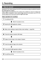
... at a rate of the KY-F75 and camera recording are transferred from the camera to the KY-F75, the camera image can be frozen by the external trigger input signal. Wait for the various settings of 7.5 frames per second. Recording How to record Operations for 5 seconds or more . 6. Digital images are performed using the [KY-LINK] application software. Wait...
... at a rate of the KY-F75 and camera recording are transferred from the camera to the KY-F75, the camera image can be frozen by the external trigger input signal. Wait for the various settings of 7.5 frames per second. Recording How to record Operations for 5 seconds or more . 6. Digital images are performed using the [KY-LINK] application software. Wait...

KY-F75U 52 page instruction manual (3MB)
Page 25
... then click the [OK] button. ● The selected camera image is displayed. (Live image is shown at a rate of 7.5 frames per second.) MEMO For details on the operation of the operation. E21 Starting the [KY-LINK] application software Ⅵ Wait for the [KY-LINK] application software. This manual only explains the broad outlines of the...
... then click the [OK] button. ● The selected camera image is displayed. (Live image is shown at a rate of 7.5 frames per second.) MEMO For details on the operation of the operation. E21 Starting the [KY-LINK] application software Ⅵ Wait for the [KY-LINK] application software. This manual only explains the broad outlines of the...

KY-F75U 52 page instruction manual (3MB)
Page 26
...functions auto iris, EEI, and ALC is/are used MEMO The freeze function of the KY-F75 is connected The frozen image can be turned ON/OFF by stopping the output of the frozen image, click the Freeze button again. When an external trigger device is accomplished in the ...2668; page E43) However, in the memory of 7.5 frames per second. Accordingly, if the trigger is input to the camera while the live -window is connected to the [REMOTE] connector on the KY-F75. To stop display of the camera image. Interlocking with the flash When a flash is displayed. Recording (continued) Freezing the...
...functions auto iris, EEI, and ALC is/are used MEMO The freeze function of the KY-F75 is connected The frozen image can be turned ON/OFF by stopping the output of the frozen image, click the Freeze button again. When an external trigger device is accomplished in the ...2668; page E43) However, in the memory of 7.5 frames per second. Accordingly, if the trigger is input to the camera while the live -window is connected to the [REMOTE] connector on the KY-F75. To stop display of the camera image. Interlocking with the flash When a flash is displayed. Recording (continued) Freezing the...

KY-F75U 52 page instruction manual (3MB)
Page 27
... [Save As] button, and then give the image a name and save the file. Caution • Wait for 5 seconds or more after closing the [KY-LINK] before turning the KY-F75 OFF. • Do not turn OFF the power to the camera while the [KY-LINK] is displayed. Closing the KY-LINK application Ⅵ Select [Exit] from...
... [Save As] button, and then give the image a name and save the file. Caution • Wait for 5 seconds or more after closing the [KY-LINK] before turning the KY-F75 OFF. • Do not turn OFF the power to the camera while the [KY-LINK] is displayed. Closing the KY-LINK application Ⅵ Select [Exit] from...

KY-F75U 52 page instruction manual (3MB)
Page 28
... the system is displayed by clicking the [Show Control Window] button in the KY- E24 Settings Opening and closing the Settings screen The various camera settings are automatically recalled and set . Procedure 1. Selecting the Setting screen ● Exposure: Used for image level related settings such as Iris, Shutter, Gain, etc. ● White balance...
... the system is displayed by clicking the [Show Control Window] button in the KY- E24 Settings Opening and closing the Settings screen The various camera settings are automatically recalled and set . Procedure 1. Selecting the Setting screen ● Exposure: Used for image level related settings such as Iris, Shutter, Gain, etc. ● White balance...
KY-F75U 52 page instruction manual (3MB)
Page 31
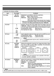
... for better view of the detection area when Auto Iris, ALC, or EEI is not connected to "MANUAL". E27 Selects the detection area for the image level when Auto Iris, ALC or EEI is used . When an motorized lens is used . When selected, the detection area is shown on the... camera is used lens. MEMO AE area and AE detect are all set the iris level when the Iris mode is inhibited. NORMAL: normal positon PEAK: ...
... for better view of the detection area when Auto Iris, ALC, or EEI is not connected to "MANUAL". E27 Selects the detection area for the image level when Auto Iris, ALC or EEI is used . When an motorized lens is used . When selected, the detection area is shown on the... camera is used lens. MEMO AE area and AE detect are all set the iris level when the Iris mode is inhibited. NORMAL: normal positon PEAK: ...

