Instructions
Page 1
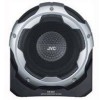
Model No. ENGLISH ACTIVE SUBWOOFER SYSTEM SYTÈME DE CAISSON DE GRAVE ACTIF SISTEMA DE SUBWOOFER ACTIVO CS-DA1 FRANÇAIS ESPANÕL INSTRUCTIONS MANUEL D'INSTRUCTIONS MANUAL DE INSTRUCCIONES For Customer Use: Enter the Model No. which are located on the top or bottom of the cabinet. LVT1554-003A [J] Retain this information for future reference. Serial No. and Serial No.
Model No. ENGLISH ACTIVE SUBWOOFER SYSTEM SYTÈME DE CAISSON DE GRAVE ACTIF SISTEMA DE SUBWOOFER ACTIVO CS-DA1 FRANÇAIS ESPANÕL INSTRUCTIONS MANUEL D'INSTRUCTIONS MANUAL DE INSTRUCCIONES For Customer Use: Enter the Model No. which are located on the top or bottom of the cabinet. LVT1554-003A [J] Retain this information for future reference. Serial No. and Serial No.
Instructions
Page 2
... unit. • When replacing the fuse, only use a 15 A fuse. • Do not let foreign objects get inside . [European Union only] G-1 If this subwoofer system with the volume on 12 V DC, NEGATIVE ground electrical systems. • To prevent short circuits, we recommend that interference will block outside sounds, making driving dangerous. However, there is no user serviceable parts inside the unit...
... unit. • When replacing the fuse, only use a 15 A fuse. • Do not let foreign objects get inside . [European Union only] G-1 If this subwoofer system with the volume on 12 V DC, NEGATIVE ground electrical systems. • To prevent short circuits, we recommend that interference will block outside sounds, making driving dangerous. However, there is no user serviceable parts inside the unit...

Instructions
Page 5
ENGLISH TABLE OF CONTENTS TABLE OF CONTENTS 1 ACCESSORIES 2 PHASE AND SOUND ADJUSTMENT 3 INSTALLATION 5 CONNECTIONS 9 TROUBLE SHOOTING 13 SPECIFICATIONS 14 DIMENSIONS 14 1
ENGLISH TABLE OF CONTENTS TABLE OF CONTENTS 1 ACCESSORIES 2 PHASE AND SOUND ADJUSTMENT 3 INSTALLATION 5 CONNECTIONS 9 TROUBLE SHOOTING 13 SPECIFICATIONS 14 DIMENSIONS 14 1
Instructions
Page 6
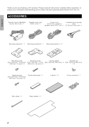
... instructions carefully before operation, to ensure your complete understanding and to obtain the best possible performance from the unit. ACCESSORIES Remote control: RM-RK82 (Cord: 16 ft / 5 m) c 1 Speaker input cord (13 ft / 4 m) c 1 Power cord L-shaped pin plug relay (19 ft / 6 m, Length of cord speaker input 3.3 ft / 1 m) c 1 (7-7/8 inch / 200 mm) c 1 Mounting bracket A c 1 Mounting bracket B c 1 Mounting bracket C c 2 Mounting screw Mounting screw Spring washer Butterfly nut (Dia. 7/32 inch c 11/32 inch...
... instructions carefully before operation, to ensure your complete understanding and to obtain the best possible performance from the unit. ACCESSORIES Remote control: RM-RK82 (Cord: 16 ft / 5 m) c 1 Speaker input cord (13 ft / 4 m) c 1 Power cord L-shaped pin plug relay (19 ft / 6 m, Length of cord speaker input 3.3 ft / 1 m) c 1 (7-7/8 inch / 200 mm) c 1 Mounting bracket A c 1 Mounting bracket B c 1 Mounting bracket C c 2 Mounting screw Mounting screw Spring washer Butterfly nut (Dia. 7/32 inch c 11/32 inch...

Instructions
Page 7
...that bass tones can be heard even when the volume is monaural. When it is on and off the subwoofer output. Connects the power cord. switch Normally, set this when connecting to the position (a/b) Switches the cutoff frequency. which gives you better sound. LINE IN terminal Use this...lights up. ON: Blue, OFF: Green Volume ⅐ Adjust the subwoofer output level. ⅐ Adjust the sound within the acceptable range (no distortion). 3 PHASE switch LPF (Low Pass Filter) switch POWER/SPEAKER INPUT terminal Switch to the line output or subwoofer output of the car stereo.
...that bass tones can be heard even when the volume is monaural. When it is on and off the subwoofer output. Connects the power cord. switch Normally, set this when connecting to the position (a/b) Switches the cutoff frequency. which gives you better sound. LINE IN terminal Use this...lights up. ON: Blue, OFF: Green Volume ⅐ Adjust the subwoofer output level. ⅐ Adjust the sound within the acceptable range (no distortion). 3 PHASE switch LPF (Low Pass Filter) switch POWER/SPEAKER INPUT terminal Switch to the line output or subwoofer output of the car stereo.
Instructions
Page 8
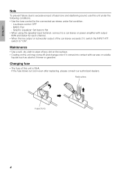
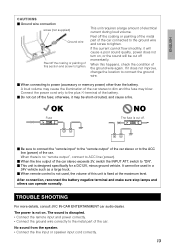
... failure due to excessive input of bass tone and deafening sound, use this unit under the following conditions. • Use the tone control for each channel. • When the line output or subwoofer output of this unit is 15 A. Maintenance • Use a soft, dry cloth to wipe... output 60W and below for the connected car stereo under flat condition. ⅐ Loudness control: OFF ⅐ BASS: Flat ⅐ Graphic equalizer: Set bass to flat • When using the speaker input terminal, connect to AONB. switch to a car stereo or power amplifier with car wax or volatile liquids such as...
... failure due to excessive input of bass tone and deafening sound, use this unit under the following conditions. • Use the tone control for each channel. • When the line output or subwoofer output of this unit is 15 A. Maintenance • Use a soft, dry cloth to wipe... output 60W and below for the connected car stereo under flat condition. ⅐ Loudness control: OFF ⅐ BASS: Flat ⅐ Graphic equalizer: Set bass to flat • When using the speaker input terminal, connect to AONB. switch to a car stereo or power amplifier with car wax or volatile liquids such as...
Instructions
Page 9
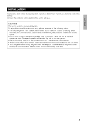
terminal cord of the car stereo. • This unit generates a strong magnetic field. Disregarding safety while using the unit is very dangerous. • Before mounting, be sure to secure or place this unit at the back passenger seat. terminal cord of the battery. • When connecting to a car stereo, please also refer to the instruction manual of the battery. CAUTION This unit is very...
terminal cord of the car stereo. • This unit generates a strong magnetic field. Disregarding safety while using the unit is very dangerous. • Before mounting, be sure to secure or place this unit at the back passenger seat. terminal cord of the battery. • When connecting to a car stereo, please also refer to the instruction manual of the battery. CAUTION This unit is very...

Instructions
Page 10
... bottom. ENGLISH Procedures for horizontal installation 1 Mount mounting brackets A and B at the back of the unit Mounting bracket B Mounting screw (Dia. 7/32 inch c 11/32 inch / M 5 mm c 8 mm) c 4 Mount such that the letter AAB is at the bottom. 3 Make a hole in step 2 1-1(2/88imncmh) Use a cutter to make 4 holes. • Use the paper pattern to it Mounting bracket C 1(218-193m/3m2 )inch Mounting bracket C (c2) assembled in...
... bottom. ENGLISH Procedures for horizontal installation 1 Mount mounting brackets A and B at the back of the unit Mounting bracket B Mounting screw (Dia. 7/32 inch c 11/32 inch / M 5 mm c 8 mm) c 4 Mount such that the letter AAB is at the bottom. 3 Make a hole in step 2 1-1(2/88imncmh) Use a cutter to make 4 holes. • Use the paper pattern to it Mounting bracket C 1(218-193m/3m2 )inch Mounting bracket C (c2) assembled in...

Instructions
Page 11
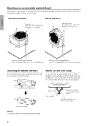
.../m32mi)nch 2-7(/5362 minmch) • Use the paper pattern to determine the position and mount the unit in the car. 1(218-193m/3m2 )inch Mounting bracket C (c2) assembled in step 2 1-1(2/88imncmh) Use a cutter to make 4 holes. • Use the paper pattern to mount the unit. ENGLISH Procedures for vertical installation 1 Mount mounting brackets A and B at the bottom of the unit comes into contact with butterfly...
.../m32mi)nch 2-7(/5362 minmch) • Use the paper pattern to determine the position and mount the unit in the car. 1(218-193m/3m2 )inch Mounting bracket C (c2) assembled in step 2 1-1(2/88imncmh) Use a cutter to make 4 holes. • Use the paper pattern to mount the unit. ENGLISH Procedures for vertical installation 1 Mount mounting brackets A and B at the bottom of the unit comes into contact with butterfly...
Instructions
Page 12
...; Clean the item thoroughly before attaching. How to use screws to vibration, secure all cords with the attached wire clamp after all connection is completed. Double-sided tape Peel off due to secure the unit on the commercially available board. Horizontal installation Vertical installation Tapping screw (Dia. 3/16 inch c 13/16 inch / M 4 mm c 20 mm) c 4 Tapping screw (Dia. 3/16...
...; Clean the item thoroughly before attaching. How to use screws to vibration, secure all cords with the attached wire clamp after all connection is completed. Double-sided tape Peel off due to secure the unit on the commercially available board. Horizontal installation Vertical installation Tapping screw (Dia. 3/16 inch c 13/16 inch / M 4 mm c 20 mm) c 4 Tapping screw (Dia. 3/16...
Instructions
Page 13
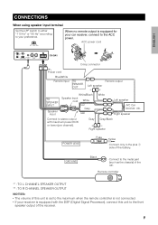
... to the metal part (such as the chassis) of the car. Remote controller 1 : TO L CHANNEL SPEAKER OUTPUT 2 : TO R CHANNEL SPEAKER OUTPUT NOTES: • The volume of this unit is set to the maximum when the remote controller is not connected. • If your receiver is equipped for your preference. ACC power cord ENGLISH CS-DA1 Crimp connector Power cord Blue/White Remote input...
... to the metal part (such as the chassis) of the car. Remote controller 1 : TO L CHANNEL SPEAKER OUTPUT 2 : TO R CHANNEL SPEAKER OUTPUT NOTES: • The volume of this unit is set to the maximum when the remote controller is not connected. • If your receiver is equipped for your preference. ACC power cord ENGLISH CS-DA1 Crimp connector Power cord Blue/White Remote input...
Instructions
Page 14
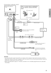
... your car receiver, connect to the ACC power. ACC power cord L-shaped pin plug relay cord CS-DA1 Crimp connector Power cord Blue/White Remote input TO REMOTE OUT Remote output TO SPEAKER INPUT Speaker input This is not used when LINE IN terminal is equipped with the DSP (Digital Signal Processor), connect this unit is set to the plus + side of the car. Pin cord (not...
... your car receiver, connect to the ACC power. ACC power cord L-shaped pin plug relay cord CS-DA1 Crimp connector Power cord Blue/White Remote input TO REMOTE OUT Remote output TO SPEAKER INPUT Speaker input This is not used when LINE IN terminal is equipped with the DSP (Digital Signal Processor), connect this unit is set to the plus + side of the car. Pin cord (not...
Instructions
Page 15
..., connect to Lch. JVC Car receiver, etc. ACC power cord L-shaped pin plug relay cord CS-DA1 Crimp connector Power cord Blue/White Remote input TO REMOTE OUT Remote output TO SPEAKER INPUT Speaker input This is not used when LINE IN terminal is used with vinyl tapes. 11 Pin cord (not supplied) Subwoofer output POWER LEAD Fuse 15A Yellow ⅐ Connect only to the metal part (such...
..., connect to Lch. JVC Car receiver, etc. ACC power cord L-shaped pin plug relay cord CS-DA1 Crimp connector Power cord Blue/White Remote input TO REMOTE OUT Remote output TO SPEAKER INPUT Speaker input This is not used when LINE IN terminal is used with vinyl tapes. 11 Pin cord (not supplied) Subwoofer output POWER LEAD Fuse 15A Yellow ⅐ Connect only to the metal part (such...

Instructions
Page 16
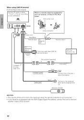
... the ACC power. When no remote output is used with vinyl tapes. 12 ENGLISH [Connecting to 5.1ch subwoofer output] Set the LPF switch to adjust the volume of the unit. (However, when the sound of the car. ACC power cord L-shaped pin plug relay cord CS-DA1 Crimp connector Power cord Blue/White Remote input TO REMOTE OUT Remote output TO SPEAKER INPUT Speaker input This...
... the ACC power. When no remote output is used with vinyl tapes. 12 ENGLISH [Connecting to 5.1ch subwoofer output] Set the LPF switch to adjust the volume of the unit. (However, when the sound of the car. ACC power cord L-shaped pin plug relay cord CS-DA1 Crimp connector Power cord Blue/White Remote input TO REMOTE OUT Remote output TO SPEAKER INPUT Speaker input This...
Instructions
Page 17
... fuse is designed specifically for a DC12V, minus ground vehicle. When this happens, check the condition of the car connected to the ground wire and screw to "ON". Ⅵ This unit is cut off momentarily. switch to tighten. It cannot be used in a 24V vehicle such as a large truck. Ⅵ When remote control is not used, the volume of this...
... fuse is designed specifically for a DC12V, minus ground vehicle. When this happens, check the condition of the car connected to the ground wire and screw to "ON". Ⅵ This unit is cut off momentarily. switch to tighten. It cannot be used in a 24V vehicle such as a large truck. Ⅵ When remote control is not used, the volume of this...
Instructions
Page 18
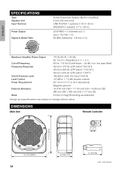
...) (Excluding accessories) Design and specifications are subject to -Noise Ratio Active Subwoofer System (Built-in amplifier) 8 inch (20 cm) cone LINE IN (RCA 1 system), 0.19 V / 25 k& SPEAKER (1 system), 3.7 V / 20 k& 32 W RMS c 2 channels at 2 & and ≤ 1% THD a N 80 dBA (reference: 1 W into 2 &) Maximum Amplifier Power Output Cut-off Frequency Frequency Response Sound Pressure Level Level Control Power Requirement External dimension Mass 170 W (85 W a 85...
...) (Excluding accessories) Design and specifications are subject to -Noise Ratio Active Subwoofer System (Built-in amplifier) 8 inch (20 cm) cone LINE IN (RCA 1 system), 0.19 V / 25 k& SPEAKER (1 system), 3.7 V / 20 k& 32 W RMS c 2 channels at 2 & and ≤ 1% THD a N 80 dBA (reference: 1 W into 2 &) Maximum Amplifier Power Output Cut-off Frequency Frequency Response Sound Pressure Level Level Control Power Requirement External dimension Mass 170 W (85 W a 85...

Instructions
Page 48
EN, FR, SP ᮊ 2007 Victor Company of Japan, Limited 0507SKMSANJEIN ACTIVE SUBWOOFER SYSTEM CS-DA1
EN, FR, SP ᮊ 2007 Victor Company of Japan, Limited 0507SKMSANJEIN ACTIVE SUBWOOFER SYSTEM CS-DA1
