User Guide
Page 7
... Specification. For the latest version of this server system. This includes how to navigate through the BIOS Setup screens, how to perform a BIOS update, and how to add and replace components on using the Intel® Server System SR1530AH / SR1530AHLX / SR1530HAHLX. Chapter 3 provides instructions on page x for troubleshooting, upgrading, and repairing this manual, see http:// support.intel.com/support/motherboards/server/S3000AH/. See Table 1 on adding and replacing components. Preface About this Manual...
... Specification. For the latest version of this server system. This includes how to navigate through the BIOS Setup screens, how to perform a BIOS update, and how to add and replace components on using the Intel® Server System SR1530AH / SR1530AHLX / SR1530HAHLX. Chapter 3 provides instructions on page x for troubleshooting, upgrading, and repairing this manual, see http:// support.intel.com/support/motherboards/server/S3000AH/. See Table 1 on adding and replacing components. Preface About this Manual...

User Guide
Page 10
... received this product and need to install it Intel® Server Chassis SR1530 Technical Product Specification Found at: http://support.intel.com/support/motherboards/server/ S3000AH/ Intel® Server Board S3000AH Technical Product Specification Found at: http://support.intel.com/support/motherboards/server/ S3000AH/ Intel® Server System SR1530AH / SR1530AHLX / SR1530HAHLX Quick Start User's Guide Found in the product box Virtual system tours and interactive repair information A link to the SMaRT Tool is available under "Other...
... received this product and need to install it Intel® Server Chassis SR1530 Technical Product Specification Found at: http://support.intel.com/support/motherboards/server/ S3000AH/ Intel® Server Board S3000AH Technical Product Specification Found at: http://support.intel.com/support/motherboards/server/ S3000AH/ Intel® Server System SR1530AH / SR1530AHLX / SR1530HAHLX Quick Start User's Guide Found in the product box Virtual system tours and interactive repair information A link to the SMaRT Tool is available under "Other...

User Guide
Page 13
... the PCI Cooling Fan (SR1530AH/SR1530AHLX 89 Replacing a Cooling Fan (SR1530HAHLX 91 Replacing the System Blower Fans (SR1530HAHLX 91 Installing and Removing the Rack Handles 93 Installing the Rack Handles 93 Removing the Rack Handles 94 Appendix A: Technical Reference 95 Cable Routing ...95 Power Cable Routing (SR1530AH / SR1530AHLX 96 Data Cable Routing (SR1530AH / SR1530AHLX 97 Cable Routing (SR1530HAHLX 98 350W Single Power Supply Input Voltages 99 350W Single Power Supply Output Voltages 99 System Environmental Specifications 100 Appendix B: Troubleshooting 101 Resetting...
... the PCI Cooling Fan (SR1530AH/SR1530AHLX 89 Replacing a Cooling Fan (SR1530HAHLX 91 Replacing the System Blower Fans (SR1530HAHLX 91 Installing and Removing the Rack Handles 93 Installing the Rack Handles 93 Removing the Rack Handles 94 Appendix A: Technical Reference 95 Cable Routing ...95 Power Cable Routing (SR1530AH / SR1530AHLX 96 Data Cable Routing (SR1530AH / SR1530AHLX 97 Cable Routing (SR1530HAHLX 98 350W Single Power Supply Input Voltages 99 350W Single Power Supply Output Voltages 99 System Environmental Specifications 100 Appendix B: Troubleshooting 101 Resetting...

User Guide
Page 17
Setup Menu Key Use 20 Table 5. List of Tables Table 1. System Environmental Specifications 100 Table 7. POST Error Beep Codes 110 Table 10. Server System References x Table 2. NIC LED Descriptions 7 Table 4. Resetting the System 101 Table 8. LED Information ...110 Table 9. Product Regulatory Compliance Markings 149 Intel® Server System SR1530AH / SR1530AHLX xvii Intel® Server System SR1530AH / SR1530AHLX / SR1530HAHLX Feature Summary 2 Table 3. Power Supply Output Capability 99 Table 6.
Setup Menu Key Use 20 Table 5. List of Tables Table 1. System Environmental Specifications 100 Table 7. POST Error Beep Codes 110 Table 10. Server System References x Table 2. NIC LED Descriptions 7 Table 4. Resetting the System 101 Table 8. LED Information ...110 Table 9. Product Regulatory Compliance Markings 149 Intel® Server System SR1530AH / SR1530AHLX xvii Intel® Server System SR1530AH / SR1530AHLX / SR1530HAHLX Feature Summary 2 Table 3. Power Supply Output Capability 99 Table 6.

User Guide
Page 20
.... Installing the PCI Cooling Fan (SR1530AH/SR1530AHLX 56 Figure 53. Removing Riser Card from Mounting Pegs (SR1530AH/SR1530AHLX 54 Figure 49. Installing an Add-In Card 65 Figure 62. Removing Power Supply from the Server System (SR1530AH/SR1530AHLX).. 79 Figure 73. Removing Front Panel Board from the Server System (SR1530AH / SR1530AHLX).. 74 Figure 68. Removing the PCI Cooling Fan (SR1530AH/SR1530AHLX 90 Figure 84. Installing the Rack Handle 93 xx Intel® Server...
.... Installing the PCI Cooling Fan (SR1530AH/SR1530AHLX 56 Figure 53. Removing Riser Card from Mounting Pegs (SR1530AH/SR1530AHLX 54 Figure 49. Installing an Add-In Card 65 Figure 62. Removing Power Supply from the Server System (SR1530AH/SR1530AHLX).. 79 Figure 73. Removing Front Panel Board from the Server System (SR1530AH / SR1530AHLX).. 74 Figure 68. Removing the PCI Cooling Fan (SR1530AH/SR1530AHLX 90 Figure 84. Installing the Rack Handle 93 xx Intel® Server...

User Guide
Page 25
...* riser card • One low-profile riser slot supporting a 1U PCI-X* riser card SATA support, 3 Gb/s: capable of supporting up to two drives (SR1530AH / SR1530AHLX) or three drives (SR1530HAHLX) • Slimline bay for IDE optical drive (optional) • One USB port • Power / sleep button • Status LED • Power LED • Hard drive activity LED • NIC1 activity LED • NIC2 activity LED One 350-watt power supply module • Three non-redundant fans...
...* riser card • One low-profile riser slot supporting a 1U PCI-X* riser card SATA support, 3 Gb/s: capable of supporting up to two drives (SR1530AH / SR1530AHLX) or three drives (SR1530HAHLX) • Slimline bay for IDE optical drive (optional) • One USB port • Power / sleep button • Status LED • Power LED • Hard drive activity LED • NIC1 activity LED • NIC2 activity LED One 350-watt power supply module • Three non-redundant fans...

User Guide
Page 32
... by Intel, use order code AXXSCD. See Table 1 on page 50. 10 Intel® Server System SR1530AH / SR1530AHLX / SR1530HAHLX For installation instructions for an optical drive, see "Installing or Removing a Slimline Optical Drive (SR1530AH / SR1530AHLX)" on page x for these drives. To use the slimline CD-ROM drive provided by Intel, use order code AXXDVDCDR. Note: The Intel® Server System SR1530AH / SR1530AHLX / SR1530HAHLX does not support all...
... by Intel, use order code AXXSCD. See Table 1 on page 50. 10 Intel® Server System SR1530AH / SR1530AHLX / SR1530HAHLX For installation instructions for an optical drive, see "Installing or Removing a Slimline Optical Drive (SR1530AH / SR1530AHLX)" on page x for these drives. To use the slimline CD-ROM drive provided by Intel, use order code AXXDVDCDR. Note: The Intel® Server System SR1530AH / SR1530AHLX / SR1530HAHLX does not support all...

User Guide
Page 44
...: Review the instructions and release notes that are provided in the readme file that you performed the upgrade. When the update completes, remove the bootable media from which you enter Setup, check your settings, save your hard drive. See "Server System References" on your settings, and exit Setup. 22 Intel® Server System SR1530AH / SR1530AHLX / SR1530HAHLX Obtaining the Upgrade Download the BIOS image file to a temporary folder on page x for a link...
...: Review the instructions and release notes that are provided in the readme file that you performed the upgrade. When the update completes, remove the bootable media from which you enter Setup, check your settings, save your hard drive. See "Server System References" on your settings, and exit Setup. 22 Intel® Server System SR1530AH / SR1530AHLX / SR1530HAHLX Obtaining the Upgrade Download the BIOS image file to a temporary folder on page x for a link...

User Guide
Page 63
... instructions, see "Removing the Server System Cover" on page 45 for an Internet link to the system, turn off all peripheral devices connected to a list of the chassis. The HDD0 drive bay is at the right side of supported hardware. Return to use. Locate the drive position you are NOT hot swappable. Installing and Removing a Hard Drive (SR1530AH / SR1530AHLX) Caution: The hard drives are replacing...
... instructions, see "Removing the Server System Cover" on page 45 for an Internet link to the system, turn off all peripheral devices connected to a list of the chassis. The HDD0 drive bay is at the right side of supported hardware. Return to use. Locate the drive position you are NOT hot swappable. Installing and Removing a Hard Drive (SR1530AH / SR1530AHLX) Caution: The hard drives are replacing...

User Guide
Page 83
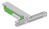
... Figure 58. See your server system. 1. Connect any cables to add or replace a PCI add-in card, see "Installing the Server System Cover". Installing the PCI Riser Assembly Note: For clarity, the figure in card requirements. 5. If you removed the PCI riser assembly for information and add-in this series of the server system. If you need to add-in card. Lower the riser assembly into your add-in card documentation for another procedure, continue with...
... Figure 58. See your server system. 1. Connect any cables to add or replace a PCI add-in card, see "Installing the Server System Cover". Installing the PCI Riser Assembly Note: For clarity, the figure in card requirements. 5. If you removed the PCI riser assembly for information and add-in this series of the server system. If you need to add-in card. Lower the riser assembly into your add-in card documentation for another procedure, continue with...

User Guide
Page 85
... 65. 7. Installing Riser Card onto Riser Assembly 8. 8. Remove the PCI riser assembly. For instructions, see "Installing a PCI Riser Card" on page 61. 10. For instructions, see "Installing the PCI Riser Assembly" on page 63. 9. Use two screws to attach the riser card to the riser assembly. AF001060 Figure 60. Install an PCI add-in card requirements. For instructions, see "Removing a PCI Add-in cards that require them. See your add-in card documentation for information and add-in card if desired. Intel® Server System SR1530AH...
... 65. 7. Installing Riser Card onto Riser Assembly 8. 8. Remove the PCI riser assembly. For instructions, see "Installing a PCI Riser Card" on page 61. 10. For instructions, see "Installing the PCI Riser Assembly" on page 63. 9. Use two screws to attach the riser card to the riser assembly. AF001060 Figure 60. Install an PCI add-in card requirements. For instructions, see "Removing a PCI Add-in cards that require them. See your add-in card documentation for information and add-in card if desired. Intel® Server System SR1530AH...

User Guide
Page 87
... use caution so you do not twist or bend the card. Push the add-in the riser assembly. Observe the safety and ESD precautions at the rear of this screw. See letter "A" in Card 1. Plug all peripheral devices and the AC power cable. 3. Removing a PCI Add-in the figure. Intel® Server System SR1530AH / SR1530AHLX / SR1530HAHLX 65 5. See letter "A" in the figure. Save...
... use caution so you do not twist or bend the card. Push the add-in the riser assembly. Observe the safety and ESD precautions at the rear of this screw. See letter "A" in Card 1. Plug all peripheral devices and the AC power cable. 3. Removing a PCI Add-in the figure. Intel® Server System SR1530AH / SR1530AHLX / SR1530HAHLX 65 5. See letter "A" in the figure. Save...

User Guide
Page 98
... the AC power cable into the server. 76 Intel® Server System SR1530AH / SR1530AHLX / SR1530HAHLX Connect the power supply cables to power supply ✧ HDD0 power connector, if a hard drive is installed here. Use the center connector on the power supply . Use the end connector on the cable ✧ Optical drive power, if an optical drive is installed. Install the server system cover. See Figure 68. - B: 2x12 main power connector - For instructions, see "Installing the Server System...
... the AC power cable into the server. 76 Intel® Server System SR1530AH / SR1530AHLX / SR1530HAHLX Connect the power supply cables to power supply ✧ HDD0 power connector, if a hard drive is installed here. Use the center connector on the power supply . Use the end connector on the cable ✧ Optical drive power, if an optical drive is installed. Install the server system cover. See Figure 68. - B: 2x12 main power connector - For instructions, see "Installing the Server System...

User Guide
Page 123
... drivers, network drivers, and SATA drivers. Resetting the System To do this software. Turn the system power off /on . In addition to the server firmware and files, also update any issue, first ensure you have installed in -depth troubleshooting, attempt first to the software updates. For any drivers used for a link to this Soft boot reset to a stable state Press Reset button Power off and then on button Remove AC power from the server for BIOS, the Baseboard Management Controller...
... drivers, network drivers, and SATA drivers. Resetting the System To do this software. Turn the system power off /on . In addition to the server firmware and files, also update any issue, first ensure you have installed in -depth troubleshooting, attempt first to the software updates. For any drivers used for a link to this Soft boot reset to a stable state Press Reset button Power off and then on button Remove AC power from the server for BIOS, the Baseboard Management Controller...

User Guide
Page 124
... a hard disk drive, is a less frequent cause. Check the tested memory, and chassis lists, as well as the supported hardware and operating system list. If the problem you press the system power on/off switch on the front panel to turn the server on (power on add-in Setup correct? • Is the operating system properly loaded? To check these settings, refer to the tested component lists. 102 Intel...
... a hard disk drive, is a less frequent cause. Check the tested memory, and chassis lists, as well as the supported hardware and operating system list. If the problem you press the system power on/off switch on the front panel to turn the server on (power on add-in Setup correct? • Is the operating system properly loaded? To check these settings, refer to the tested component lists. 102 Intel...

User Guide
Page 128
... failed? • Are the fan power connectors properly connected to the server board? • Is the cable from the control panel board connected to the both the control panel board and to the server board? • Are the power supply cables properly connected to an overheating situation? • Have your fans speeded up in incorrectly. See "Server System References" on light lit? Use the server management subsystem to check the fan status. • Have your fans speeded...
... failed? • Are the fan power connectors properly connected to the server board? • Is the cable from the control panel board connected to the both the control panel board and to the server board? • Are the power supply cables properly connected to an overheating situation? • Have your fans speeded up in incorrectly. See "Server System References" on light lit? Use the server management subsystem to check the fan status. • Have your fans speeded...

User Guide
Page 129
... the hub port is configured for the same duplex mode as the network controller. • Make sure the correct networking software is installed. • If you will need a crossover cable. • Check the network controller LEDs next to the current version. • Make sure the other PCI drivers. See the documentation that came with your operating system supports shared interrupts. • Try reseating the add-in adapter. The add-in adapter stopped working when an add...
... the hub port is configured for the same duplex mode as the network controller. • Make sure the correct networking software is installed. • If you will need a crossover cable. • Check the network controller LEDs next to the current version. • Make sure the other PCI drivers. See the documentation that came with your operating system supports shared interrupts. • Try reseating the add-in adapter. The add-in adapter stopped working when an add...

User Guide
Page 130
... try running the software from the server. Before installing a PCI card, you are intermittent, there may be caused by using the power button on the front panel. Make sure all necessary files are installed. • If the problems are running correctly sometimes indicate equipment failure. System Boots when Installing PCI Card System Management features require full-time "standby" power. See the software documentation. • Use only an authorized copy. Check the following...
... try running the software from the server. Before installing a PCI card, you are intermittent, there may be caused by using the power button on the front panel. Make sure all necessary files are installed. • If the problems are running correctly sometimes indicate equipment failure. System Boots when Installing PCI Card System Management features require full-time "standby" power. See the software documentation. • Use only an authorized copy. Check the following...

User Guide
Page 131
... power budget for a link to the current drivers and chipset files. See "Server System References" on your power line. Note: Random errors in data files: If you are set correctly. If you are getting random errors in BIOS Setup. • Make sure the drive is connected correctly and that the master/slave settings are experiencing any of the drivers for a link to software to user commands. See your drive documentation for your data files...
... power budget for a link to the current drivers and chipset files. See "Server System References" on your power line. Note: Random errors in data files: If you are set correctly. If you are getting random errors in BIOS Setup. • Make sure the drive is connected correctly and that the master/slave settings are experiencing any of the drivers for a link to software to user commands. See your drive documentation for your data files...
User Guide
Page 132
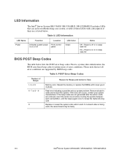
... BIOS uses these LEDs with known good modules. POST Error Beep Codes Number of their use is being used, the server board may be faulty. 110 Intel® Server System SR1530AH / SR1530AHLX / SR1530HAHLX A table of these beep codes to inform users of error conditions. Remove all error conditions are supported by BIOS beep codes. Table 8. If the beep codes are not generated after the add-in cards and re-start the system. Replace or...
... BIOS uses these LEDs with known good modules. POST Error Beep Codes Number of their use is being used, the server board may be faulty. 110 Intel® Server System SR1530AH / SR1530AHLX / SR1530HAHLX A table of these beep codes to inform users of error conditions. Remove all error conditions are supported by BIOS beep codes. Table 8. If the beep codes are not generated after the add-in cards and re-start the system. Replace or...
