Product Guide
Page 3
...Your Kit Includes ...7 Items You Must Purchase Separately 7 Feature Summary...8 System Components...8 Chassis Front Panel and Peripheral Bays 9 Chassis Back I/O Ports and Features 10 Front Panel Controls and Indicators 11 Peripherals ...13 Hot Swappable SCSI Hard Drives 13 Flex Bay...14 500 Watt Redundant Power Supply 14 480 Watt Power... the Cover...21 Remove the Processor Air Duct 22 Remove the Riser Cards 23 Remove the Fan module 24 Install the Server Board 25 Routing Cables ...28 Installing Peripherals ...34 Installing a PCI Card on a Riser Card 35 Installing the Riser Cards on the...
...Your Kit Includes ...7 Items You Must Purchase Separately 7 Feature Summary...8 System Components...8 Chassis Front Panel and Peripheral Bays 9 Chassis Back I/O Ports and Features 10 Front Panel Controls and Indicators 11 Peripherals ...13 Hot Swappable SCSI Hard Drives 13 Flex Bay...14 500 Watt Redundant Power Supply 14 480 Watt Power... the Cover...21 Remove the Processor Air Duct 22 Remove the Riser Cards 23 Remove the Fan module 24 Install the Server Board 25 Routing Cables ...28 Installing Peripherals ...34 Installing a PCI Card on a Riser Card 35 Installing the Riser Cards on the...
Product Guide
Page 7
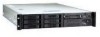
... remove and reinstall them when you install the server board. 1 Chassis Description Your Intel® SR2300 server chassis kit is designed to backplane board) • One Resource CD-ROM containing drivers, utilities, and product guide • Mounting screws (server board) • Front, mid, or ...pin (connecting front panel board to support the Intel® Server Board SE7500WV2. The fan module and riser cards are installed for shipment, but you must be purchased separately: • Front bezel (optional) • Intel Server Board SE7500WV2 (SCSI) • Minimum of one blank •...
... remove and reinstall them when you install the server board. 1 Chassis Description Your Intel® SR2300 server chassis kit is designed to backplane board) • One Resource CD-ROM containing drivers, utilities, and product guide • Mounting screws (server board) • Front, mid, or ...pin (connecting front panel board to support the Intel® Server Board SE7500WV2. The fan module and riser cards are installed for shipment, but you must be purchased separately: • Front bezel (optional) • Intel Server Board SE7500WV2 (SCSI) • Minimum of one blank •...

Product Guide
Page 10
... port OM14082 K. USB connector 1 *480 Watt redundant power supply shown. Chassis Back 10 Intel SR2300 Chassis Subassembly Product Guide Chassis Back I/O Ports and Features A BC D E O N M LKJ I . PCI card bracket (low profile) B. USB connector 2 J. RJ45 NIC 2 connector Green Status LED/Yellow Status LED C. AC power input (redundant)* G. SCSI channel A connector (If available) N. PCI card bracket (full-height...
... port OM14082 K. USB connector 1 *480 Watt redundant power supply shown. Chassis Back 10 Intel SR2300 Chassis Subassembly Product Guide Chassis Back I/O Ports and Features A BC D E O N M LKJ I . PCI card bracket (low profile) B. USB connector 2 J. RJ45 NIC 2 connector Green Status LED/Yellow Status LED C. AC power input (redundant)* G. SCSI channel A connector (If available) N. PCI card bracket (full-height...

Product Guide
Page 12
...is in a halt state for diagnostic purposes. ID button Toggles on from running. 12 Intel SR2300 Chassis Subassembly Product Guide Blinking amber light (Note 1) indicates the system is powered on standby by... the chipset. No light (Note 3) indicates no fixed disk drive activity nor fault (SCSI or IDE). Notes: 1 The Amber status takes precedence over the Green status. If the system ...be used with a paper clip or pin issues a non-maskable interrupt and puts the server in a non-critical condition. No light indicates POST/system stop. Continuous blue light indicates ...
...is in a halt state for diagnostic purposes. ID button Toggles on from running. 12 Intel SR2300 Chassis Subassembly Product Guide Blinking amber light (Note 1) indicates the system is powered on standby by... the chipset. No light (Note 3) indicates no fixed disk drive activity nor fault (SCSI or IDE). Notes: 1 The Amber status takes precedence over the Green status. If the system ...be used with a paper clip or pin issues a non-maskable interrupt and puts the server in a non-critical condition. No light indicates POST/system stop. Continuous blue light indicates ...

Product Guide
Page 13
...drive bays. DVD/CD-ROM drive/floppy disk drive module D. Hard disk drive Figure 5. Peripherals OM14084 Hot Swappable SCSI Hard Drives The chassis ships with four drive carriers for peripherals that can be purchased separately and added to install these drives, see "... Flex bay (1) C. Tape drive E. When a drive fails, the SCSI backplane detects the failure, reports it, and powers down the failed drive. The drive fault LED becomes a continuous amber light. B A A D C E A. Chassis Description 13 Hard drive bays (6) B. The following describes the available options....
...drive bays. DVD/CD-ROM drive/floppy disk drive module D. Hard disk drive Figure 5. Peripherals OM14084 Hot Swappable SCSI Hard Drives The chassis ships with four drive carriers for peripherals that can be purchased separately and added to install these drives, see "... Flex bay (1) C. Tape drive E. When a drive fails, the SCSI backplane detects the failure, reports it, and powers down the failed drive. The drive fault LED becomes a continuous amber light. B A A D C E A. Chassis Description 13 Hard drive bays (6) B. The following describes the available options....
Product Guide
Page 14
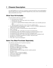
... processor(s), hard drives, and add-in the middle of sources. A fourth fan may only be added to provide cooling redundancy for cooling. 14 Intel SR2300 Chassis Subassembly Product Guide For information on installation, see "Installing a DVD drive/FDD or CD-ROM drive/FDD Module" on page 40. 500 Watt...power supply provides 500 W of 50 °C. With either the optional DVD/FDD module, CD-ROM/FDD module, or a seventh hot swappable SCSI HDD. The power supply provides 480W of the power supply; The system fans are available. The power supply contains a single fan for system components.
... processor(s), hard drives, and add-in the middle of sources. A fourth fan may only be added to provide cooling redundancy for cooling. 14 Intel SR2300 Chassis Subassembly Product Guide For information on installation, see "Installing a DVD drive/FDD or CD-ROM drive/FDD Module" on page 40. 500 Watt...power supply provides 500 W of 50 °C. With either the optional DVD/FDD module, CD-ROM/FDD module, or a seventh hot swappable SCSI HDD. The power supply provides 480W of the power supply; The system fans are available. The power supply contains a single fan for system components.

Product Guide
Page 17
Additionally, you will be sold. 2 Assembling the System Before the SR2300 can be tested, certified and/or documented to illustrate compliance to the regional regulations and laws for where the product will want to add...installed for the system. The following supplies available: • Anti-static wrist strap (recommended) • SR2300 accessory kit (included) • SE7500WV2 SCSI server board kit • Processors and memory you purchased separately to add to the server board • Optional peripherals and add-in cards you through this assembly process and create your particular...
Additionally, you will be sold. 2 Assembling the System Before the SR2300 can be tested, certified and/or documented to illustrate compliance to the regional regulations and laws for where the product will want to add...installed for the system. The following supplies available: • Anti-static wrist strap (recommended) • SR2300 accessory kit (included) • SE7500WV2 SCSI server board kit • Processors and memory you purchased separately to add to the server board • Optional peripherals and add-in cards you through this assembly process and create your particular...
Product Guide
Page 28
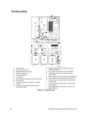
... power supply J. Fan Module 7. To server board auxiliary signal connector from server board to server board fan connectors (2) H. Fan module to backplane D. Routing Cables J 1 8 ATA66 D H G B A I . Floppy/FP/IDE flex circuit cable from power supply I C 6 E Cable Legend Data Power 7 F 2 K 2 2 or 3 4 5 1. SCSI Backplane (shown horizontal for clarity) 8. Cable Routing 28 Intel SR2300 Chassis Subassembly Product Guide Power Supply 2. To...
... power supply J. Fan Module 7. To server board auxiliary signal connector from server board to server board fan connectors (2) H. Fan module to backplane D. Routing Cables J 1 8 ATA66 D H G B A I . Floppy/FP/IDE flex circuit cable from power supply I C 6 E Cable Legend Data Power 7 F 2 K 2 2 or 3 4 5 1. SCSI Backplane (shown horizontal for clarity) 8. Cable Routing 28 Intel SR2300 Chassis Subassembly Product Guide Power Supply 2. To...
Product Guide
Page 34
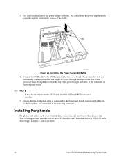
...through the notch in the bottom of the power supply air baffle, to the connector on the server board. Connect the SCSI cable to the matching connector. The following sections describe how to install PCI add-in your system...riser card is connected to the front panel board, routed over USB cable to the backplane, and connected to the SCSI connector on the backplane board. ✏ NOTE It may be purchased separately. Ensure that the front panel cable is ...disk drives, a DVD/CD-ROM drive/floppy disk drive, and a tape drive. 34 Intel SR2300 Chassis Subassembly Product Guide 3.
...through the notch in the bottom of the power supply air baffle, to the connector on the server board. Connect the SCSI cable to the matching connector. The following sections describe how to install PCI add-in your system...riser card is connected to the front panel board, routed over USB cable to the backplane, and connected to the SCSI connector on the backplane board. ✏ NOTE It may be purchased separately. Ensure that the front panel cable is ...disk drives, a DVD/CD-ROM drive/floppy disk drive, and a tape drive. 34 Intel SR2300 Chassis Subassembly Product Guide 3.

Product Guide
Page 71
... must be more then 150W. Power Usage Worksheet 1 Current (maximum) at voltage level: Device +5 Vsb +3.3 V +5 V Boards, processors, and memory (get totals from your board manual) SCSI backplane and front panel 0.40 3.5-inch drive 0.30 CD-ROM drive 0.60 3.5-inch tape drive or other peripheral 1st hot swap hard drive 2nd hot...
... must be more then 150W. Power Usage Worksheet 1 Current (maximum) at voltage level: Device +5 Vsb +3.3 V +5 V Boards, processors, and memory (get totals from your board manual) SCSI backplane and front panel 0.40 3.5-inch drive 0.30 CD-ROM drive 0.60 3.5-inch tape drive or other peripheral 1st hot swap hard drive 2nd hot...