Product Guide
Page 3
...Swappable SCSI Hard Drives 13 Flex Bay...14 500 Watt Redundant Power Supply 14 480 Watt Power Supply ...14 System Cooling ...14 Chassis Security...15 Locking and Unlocking the Front Bezel 15 2 Assembling the System Before You Begin ...17 Supplies Needed ...17 Installation/Assembly Safety Instructions 18 Use Only for ... 25 Routing Cables ...28 Installing Peripherals ...34 Installing a PCI Card on a Riser Card 35 Installing the Riser Cards on the Server Board 37 Installing a Hard Drive 38 Installing a DVD drive/FDD or CD-ROM drive/FDD Module 40 Finishing Installation ...41 Installing...
...Swappable SCSI Hard Drives 13 Flex Bay...14 500 Watt Redundant Power Supply 14 480 Watt Power Supply ...14 System Cooling ...14 Chassis Security...15 Locking and Unlocking the Front Bezel 15 2 Assembling the System Before You Begin ...17 Supplies Needed ...17 Installation/Assembly Safety Instructions 18 Use Only for ... 25 Routing Cables ...28 Installing Peripherals ...34 Installing a PCI Card on a Riser Card 35 Installing the Riser Cards on the Server Board 37 Installing a Hard Drive 38 Installing a DVD drive/FDD or CD-ROM drive/FDD Module 40 Finishing Installation ...41 Installing...
Product Guide
Page 4
... Add-in Card 50 Replacing a 480 Watt Power Supply Module 53 Replacing a Power Supply Cage 54 Installing a Redundant Fan 56 Replacing the Fan Module 58 Replacing a Backplane Board 59 Replacing a Front Panel Board 60 Replacing a Server Board 61 A Regulatory and Certification Information Product ... Power Usage 71 Worksheet, Calculating DC Power Usage 71 Worksheet, Total Combined Power Used by the System 72 C Safety Warnings WARNING: English (US 74 AVERTISSEMENT: Français 76 WARNUNG: Deutsch ...78 AVVERTENZA: Italiano ...80 ADVERTENCIAS: Español 82 iv Intel SR2300 Chassis ...
... Add-in Card 50 Replacing a 480 Watt Power Supply Module 53 Replacing a Power Supply Cage 54 Installing a Redundant Fan 56 Replacing the Fan Module 58 Replacing a Backplane Board 59 Replacing a Front Panel Board 60 Replacing a Server Board 61 A Regulatory and Certification Information Product ... Power Usage 71 Worksheet, Calculating DC Power Usage 71 Worksheet, Total Combined Power Used by the System 72 C Safety Warnings WARNING: English (US 74 AVERTISSEMENT: Français 76 WARNUNG: Deutsch ...78 AVVERTENZA: Italiano ...80 ADVERTENCIAS: Español 82 iv Intel SR2300 Chassis ...
Product Guide
Page 5
... Module 40 28. Installing the Power Cord and Strain Relief Strap 41 29. Removing the Cover 21 7. Mounting the Server Board SE7500WV2 26 11. Installing the Fan module 30 15. Connecting the Auxiliary Power Cables 32 20. Installing the Power Supply Air Baffle 34 22. Replacing ...Contents v Installing the Processor Duct 33 21. Chassis Front ...9 3. Connecting the Flex Circuit Cable 31 17. Removing a Hard Drive from a Carrier 48 32. Replacing a Power Supply Module 53 36. D Warranty Limited Warranty for Intel® Chassis Subassembly Products 85 Extent of Limited Warranty 85 ...
... Module 40 28. Installing the Power Cord and Strain Relief Strap 41 29. Removing the Cover 21 7. Mounting the Server Board SE7500WV2 26 11. Installing the Fan module 30 15. Connecting the Auxiliary Power Cables 32 20. Installing the Power Supply Air Baffle 34 22. Replacing ...Contents v Installing the Processor Duct 33 21. Chassis Front ...9 3. Connecting the Flex Circuit Cable 31 17. Removing a Hard Drive from a Carrier 48 32. Replacing a Power Supply Module 53 36. D Warranty Limited Warranty for Intel® Chassis Subassembly Products 85 Extent of Limited Warranty 85 ...
Product Guide
Page 7
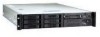
... tape drive (comes with carrier and filler panel) • One 480 W SSI PFC non-redundant power supply or a 500 W 1+0 SSI PFC redundant power supply with one module and one Intel® Xeon™ processor • Registered ECC DDR RAM memory DIMMs • SCSI hard disk ...pin (connecting front panel board to support the Intel® Server Board SE7500WV2. 1 Chassis Description Your Intel® SR2300 server chassis kit is designed to backplane board) • One Resource CD-ROM containing drivers, utilities, and product guide • Mounting screws (server board) • Front, mid, or 4-...
... tape drive (comes with carrier and filler panel) • One 480 W SSI PFC non-redundant power supply or a 500 W 1+0 SSI PFC redundant power supply with one module and one Intel® Xeon™ processor • Registered ECC DDR RAM memory DIMMs • SCSI hard disk ...pin (connecting front panel board to support the Intel® Server Board SE7500WV2. 1 Chassis Description Your Intel® SR2300 server chassis kit is designed to backplane board) • One Resource CD-ROM containing drivers, utilities, and product guide • Mounting screws (server board) • Front, mid, or 4-...
Product Guide
Page 8
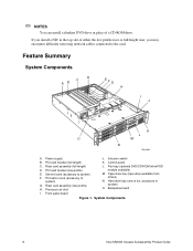
...DVD/CD-ROM drive/FDD module available) M. Tape drive bay (tape drive available from others) N. System Components 8 Intel SR2300 Chassis Subassembly Product Guide PCI card bracket (full-length) K. Processor air duct L. Control panel C. Riser card assembly (full-...to system) O. Feature Summary System Components D C AB EFG H I . Server board (accessory to system) G. PCI card bracket (low-profile) E. If you may encounter difficulty removing network cables connected to the card. Power supply J. Riser card assembly (low-profile) H. Backplane board I J K L ...
...DVD/CD-ROM drive/FDD module available) M. Tape drive bay (tape drive available from others) N. System Components 8 Intel SR2300 Chassis Subassembly Product Guide PCI card bracket (full-length) K. Processor air duct L. Control panel C. Riser card assembly (full-...to system) O. Feature Summary System Components D C AB EFG H I . Server board (accessory to system) G. PCI card bracket (low-profile) E. If you may encounter difficulty removing network cables connected to the card. Power supply J. Riser card assembly (low-profile) H. Backplane board I J K L ...

Product Guide
Page 10
... C. PS/2† mouse/keyboard connector L. RJ45 serial port OM14082 K. AC power input (primary)* F. USB connector 1 *480 Watt redundant power supply shown. PCI card bracket (full-height) E. SCSI channel A connector (If available) N. Video connector O. RJ45 NIC 1 connector M. Figure 3. Power supply module, primary* I H GF A. Chassis Back 10 Intel SR2300 Chassis Subassembly Product Guide Serial A port mounting hole (cable not provided) D. AC...
... C. PS/2† mouse/keyboard connector L. RJ45 serial port OM14082 K. AC power input (primary)* F. USB connector 1 *480 Watt redundant power supply shown. PCI card bracket (full-height) E. SCSI channel A connector (If available) N. Video connector O. RJ45 NIC 1 connector M. Figure 3. Power supply module, primary* I H GF A. Chassis Back 10 Intel SR2300 Chassis Subassembly Product Guide Serial A port mounting hole (cable not provided) D. AC...
Product Guide
Page 14
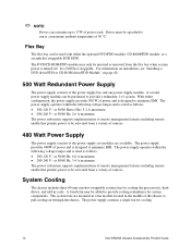
... in cards. System Cooling The chassis includes three 60-mm non-hot-swappable system fans for cooling. 14 Intel SR2300 Chassis Subassembly Product Guide ✏ NOTE Drives can consume up to 17W of the power supply bay and one power supply module. For information on installation,... see "Installing a DVD drive/FDD or CD-ROM drive/FDD Module" on page 40. 500 Watt Redundant Power Supply The power supply consists of power...
... in cards. System Cooling The chassis includes three 60-mm non-hot-swappable system fans for cooling. 14 Intel SR2300 Chassis Subassembly Product Guide ✏ NOTE Drives can consume up to 17W of the power supply bay and one power supply module. For information on installation,... see "Installing a DVD drive/FDD or CD-ROM drive/FDD Module" on page 40. 500 Watt Redundant Power Supply The power supply consists of power...

Product Guide
Page 18
...UL listing and other than ITE applications, (such as Information Technology Equipment (ITE) that could cause a short circuit 18 Intel SR2300 Chassis Subassembly Product Guide Use Only for other Product Categories and Environments other regulatory approvals will be void, and the product will ... on connectors • Sharp pins on printed circuit assemblies • Rough edges and sharp corners on the chassis • Hot components (like processors, heat sinks, and power supply modules) • Damage to meet and maintain safety and product regulatory requirements when integrating this...
...UL listing and other than ITE applications, (such as Information Technology Equipment (ITE) that could cause a short circuit 18 Intel SR2300 Chassis Subassembly Product Guide Use Only for other Product Categories and Environments other regulatory approvals will be void, and the product will ... on connectors • Sharp pins on printed circuit assemblies • Rough edges and sharp corners on the chassis • Hot components (like processors, heat sinks, and power supply modules) • Damage to meet and maintain safety and product regulatory requirements when integrating this...

Product Guide
Page 19
... 19 Warnings and Cautions These warnings and cautions apply whenever you remove the chassis cover to the server. 2. Only a technically qualified person should integrate and configure the server. Then unplug all telecommunication lines connected to I/O connectors or ports on the power supply must be an IEC 320, sheet C13, type female connector. • In Europe...
... 19 Warnings and Cautions These warnings and cautions apply whenever you remove the chassis cover to the server. 2. Only a technically qualified person should integrate and configure the server. Then unplug all telecommunication lines connected to I/O connectors or ports on the power supply must be an IEC 320, sheet C13, type female connector. • In Europe...

Product Guide
Page 20
... outlet or the chassis. WARNING Do not open the power supply. WARNING The power button on power, telephone, and communication cables. WARNING Hazardous electrical conditions may be present on the front panel DOES NOT turn off the server and disconnect the power cords, telecommunications systems, networks, and modems attached to qualified technical service personnel. 20 Intel SR2300 Chassis Subassembly Product...
... outlet or the chassis. WARNING Do not open the power supply. WARNING The power button on power, telephone, and communication cables. WARNING Hazardous electrical conditions may be present on the front panel DOES NOT turn off the server and disconnect the power cords, telecommunications systems, networks, and modems attached to qualified technical service personnel. 20 Intel SR2300 Chassis Subassembly Product...

Product Guide
Page 24
At the end of the fan module closest to the chassis centerline, push on the module to release it from the chassis (A). 4. Lift the processor duct out of the chassis. 3 2 1 C B A Figure 9. Slide the module towards the power supply until it is installed, remove the 100-pin flex circuit. 3. While pushing on the tab, lift up on the tab to clear the retention stub. 5. Remove the Fan module 1. Lift the fan module out of the chassis. 2. Removing the Fan module OM14088 24 Intel SR2300 Chassis Subassembly Product Guide If it comes free. 6.
At the end of the fan module closest to the chassis centerline, push on the module to release it from the chassis (A). 4. Lift the processor duct out of the chassis. 3 2 1 C B A Figure 9. Slide the module towards the power supply until it is installed, remove the 100-pin flex circuit. 3. While pushing on the tab, lift up on the tab to clear the retention stub. 5. Remove the Fan module 1. Lift the fan module out of the chassis. 2. Removing the Fan module OM14088 24 Intel SR2300 Chassis Subassembly Product Guide If it comes free. 6.
Product Guide
Page 28
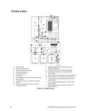
... D. To server board auxiliary power connector from power supply OM14091 C. Cable Routing 28 Intel SR2300 Chassis Subassembly Product Guide Routing Cables J 1 8 ATA66 D H G B A I . Tape Drive (optional) 5. SCSI Hard Disk Drives 3. Server Board A. To server board primary power connector from power supply J. Floppy/FP/IDE flex circuit cable from server board to server board fan connectors (2) H. Power Supply 2. Fan Module 7. To backplane power connector from power supply I C 6 E Cable Legend Data Power 7 F 2 K 2 2 or...
... D. To server board auxiliary power connector from power supply OM14091 C. Cable Routing 28 Intel SR2300 Chassis Subassembly Product Guide Routing Cables J 1 8 ATA66 D H G B A I . Tape Drive (optional) 5. SCSI Hard Disk Drives 3. Server Board A. To server board primary power connector from power supply J. Floppy/FP/IDE flex circuit cable from server board to server board fan connectors (2) H. Power Supply 2. Fan Module 7. To backplane power connector from power supply I C 6 E Cable Legend Data Power 7 F 2 K 2 2 or...

Product Guide
Page 29
...arrow (2) until they are fully seated. While pressing down on the chassis floor and the corresponding holes in the direction of the fan module. 2. Assembling the System 29 Align the holes in the area. 1. Connect the main server board power cable to the white 6-pin connector. 2. B B A OM14616 ...white 24-pin connector on the chassis and lower the fan module onto the floor. 4. Connect Power Cables 1. Firmly press the two connectors together until the latch snaps into place. Verify that the P6 backplane power cable is routed from the power supply to the backplane board and is...
...arrow (2) until they are fully seated. While pressing down on the chassis floor and the corresponding holes in the direction of the fan module. 2. Assembling the System 29 Align the holes in the area. 1. Connect the main server board power cable to the white 6-pin connector. 2. B B A OM14616 ...white 24-pin connector on the chassis and lower the fan module onto the floor. 4. Connect Power Cables 1. Firmly press the two connectors together until the latch snaps into place. Verify that the P6 backplane power cable is routed from the power supply to the backplane board and is...
Product Guide
Page 34
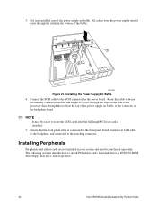
...✏ NOTE It may be purchased separately. Installing the Power Supply Air Baffle 4. 3. Installing Peripherals Peripherals and add-in cards are not included in the bottom of the power supply air baffle, to the connector on the server board. Connect the SCSI cable to route the SCSI cable.... Ensure that the front panel cable is installed. 5. All cables from the power supply should route through the notch in cards, hard disk drives, a DVD/CD-ROM drive/floppy disk drive, and a tape drive. 34 Intel SR2300 Chassis Subassembly Product Guide If it isn't installed, install the...
...✏ NOTE It may be purchased separately. Installing the Power Supply Air Baffle 4. 3. Installing Peripherals Peripherals and add-in cards are not included in the bottom of the power supply air baffle, to the connector on the server board. Connect the SCSI cable to route the SCSI cable.... Ensure that the front panel cable is installed. 5. All cables from the power supply should route through the notch in cards, hard disk drives, a DVD/CD-ROM drive/floppy disk drive, and a tape drive. 34 Intel SR2300 Chassis Subassembly Product Guide If it isn't installed, install the...

Product Guide
Page 41
... the power supply but not into the plastic loop (B) of the strain relief. 4. Pull the plastic band (C) until it tightens around the power cord. A BA D C OM14095 Figure 28. Attach the strain relief strap to the COM 1 serial port header on the server board (see Figure 3, C, on page 10). Connect the other end to the chassis...
... the power supply but not into the plastic loop (B) of the strain relief. 4. Pull the plastic band (C) until it tightens around the power cord. A BA D C OM14095 Figure 28. Attach the strain relief strap to the COM 1 serial port header on the server board (see Figure 3, C, on page 10). Connect the other end to the chassis...

Product Guide
Page 53
... all of the handle. 2. At this time, push firmly on the front of the power supply bay and either one or two power supply modules. Replacing a Power Supply Module OM14114 Working Inside Your Server 53 Replacing a 500 Watt Power Supply Module The 500 Watt redundant power supply system consists of the handle to depress the latch (Figure 35, A) that is now...
... all of the handle. 2. At this time, push firmly on the front of the power supply bay and either one or two power supply modules. Replacing a Power Supply Module OM14114 Working Inside Your Server 53 Replacing a 500 Watt Power Supply Module The 500 Watt redundant power supply system consists of the handle to depress the latch (Figure 35, A) that is now...
Product Guide
Page 54
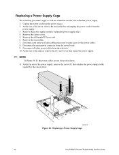
... gain access to the power cables. 8. Replacing a Power Supply Cage 54 Intel SR2300 Chassis Subassembly Product Guide At the rear of the chassis, remove the two screws (A) that attaches the power supply to both the redundant and the non-redundant power supply. 1. Disconnect and remove all other power cables from the power source. 2. Disconnect the main power connector from the power supply. 3. A C B D E OM14115 Figure 36. Remove...
... gain access to the power cables. 8. Replacing a Power Supply Cage 54 Intel SR2300 Chassis Subassembly Product Guide At the rear of the chassis, remove the two screws (A) that attaches the power supply to both the redundant and the non-redundant power supply. 1. Disconnect and remove all other power cables from the power source. 2. Disconnect the main power connector from the power supply. 3. A C B D E OM14115 Figure 36. Remove...

Product Guide
Page 55
... far as it toward the front of the server (D). Working Inside Your Server 55 Install the full-height PCI riser card. 19. Install the chassis cover. 21. Connect all cables. Lift the power supply out of the power supply. 15. 12. Lift the fan end of the power supply above the chassis standoff and slide it will go. 14. Place...
... far as it toward the front of the server (D). Working Inside Your Server 55 Install the full-height PCI riser card. 19. Install the chassis cover. 21. Connect all cables. Lift the power supply out of the power supply. 15. 12. Lift the fan end of the power supply above the chassis standoff and slide it will go. 14. Place...
Product Guide
Page 56
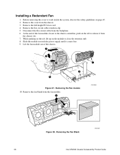
... stub. 8. At the end of the chassis. 3 2 1 C B A Figure 37. Slide the module towards the power supply until it from the backplane. 6. Installing a Redundant Fan 1. Lift the fan module out of the fan module closest to the chassis centerline, push on page 45. 2. Removing the Fan Blank OM14587 56 Intel SR2300 Chassis Subassembly Product Guide Remove the cover...
... stub. 8. At the end of the chassis. 3 2 1 C B A Figure 37. Slide the module towards the power supply until it from the backplane. 6. Installing a Redundant Fan 1. Lift the fan module out of the fan module closest to the chassis centerline, push on page 45. 2. Removing the Fan Blank OM14587 56 Intel SR2300 Chassis Subassembly Product Guide Remove the cover...
Product Guide
Page 58
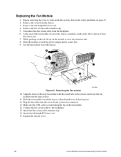
...chassis cover. 58 Intel SR2300 Chassis Subassembly Product Guide Remove the flex circuit cable retention clip. 5. Slide the module towards the power supply until it from the chassis (A). 7. While pushing on the tab, lift up on the chassis and lower the fan module onto the chassis floor. 11. Removing the Fan module 10. Plug the fan cables into the server... to clear the retention stub. 8. Remove the full-height PCI riser card. 4. Disconnect the flex circuit cable from the chassis. 3. At the end of the fan module closest to the backplane. 15. Connect the flex circuit cable to the...
...chassis cover. 58 Intel SR2300 Chassis Subassembly Product Guide Remove the flex circuit cable retention clip. 5. Slide the module towards the power supply until it from the chassis (A). 7. While pushing on the tab, lift up on the chassis and lower the fan module onto the chassis floor. 11. Removing the Fan module 10. Plug the fan cables into the server... to clear the retention stub. 8. Remove the full-height PCI riser card. 4. Disconnect the flex circuit cable from the chassis. 3. At the end of the fan module closest to the backplane. 15. Connect the flex circuit cable to the...
