Product Guide
Page 3
... What Your Kit Includes ...7 Items You Must Purchase Separately 7 Feature Summary...8 System Components...8 Chassis Front Panel and Peripheral Bays 9 Chassis Back I/O Ports and Features 10 Front Panel Controls and Indicators 11 Peripherals ...13 Hot Swappable SCSI Hard Drives 13 Flex Bay...14 500 Watt Redundant Power Supply 14 480 ... the Cover...21 Remove the Processor Air Duct 22 Remove the Riser Cards 23 Remove the Fan module 24 Install the Server Board 25 Routing Cables ...28 Installing Peripherals ...34 Installing a PCI Card on a Riser Card 35 Installing the Riser Cards on the...
... What Your Kit Includes ...7 Items You Must Purchase Separately 7 Feature Summary...8 System Components...8 Chassis Front Panel and Peripheral Bays 9 Chassis Back I/O Ports and Features 10 Front Panel Controls and Indicators 11 Peripherals ...13 Hot Swappable SCSI Hard Drives 13 Flex Bay...14 500 Watt Redundant Power Supply 14 480 ... the Cover...21 Remove the Processor Air Duct 22 Remove the Riser Cards 23 Remove the Fan module 24 Install the Server Board 25 Routing Cables ...28 Installing Peripherals ...34 Installing a PCI Card on a Riser Card 35 Installing the Riser Cards on the...
Product Guide
Page 4
... 53 Replacing a Power Supply Cage 54 Installing a Redundant Fan 56 Replacing the Fan Module 58 Replacing a Backplane Board 59 Replacing a Front Panel Board 60 Replacing a Server Board 61 A Regulatory and Certification Information Product Regulatory Compliance 63 Product Safety Compliance 63 Product EMC Compliance 63 Product Regulatory Compliance Markings 64 Electromagnetic...72 C Safety Warnings WARNING: English (US 74 AVERTISSEMENT: Français 76 WARNUNG: Deutsch ...78 AVVERTENZA: Italiano ...80 ADVERTENCIAS: Español 82 iv Intel SR2300 Chassis Subassembly Product Guide
... 53 Replacing a Power Supply Cage 54 Installing a Redundant Fan 56 Replacing the Fan Module 58 Replacing a Backplane Board 59 Replacing a Front Panel Board 60 Replacing a Server Board 61 A Regulatory and Certification Information Product Regulatory Compliance 63 Product Safety Compliance 63 Product EMC Compliance 63 Product Regulatory Compliance Markings 64 Electromagnetic...72 C Safety Warnings WARNING: English (US 74 AVERTISSEMENT: Français 76 WARNUNG: Deutsch ...78 AVVERTENZA: Italiano ...80 ADVERTENCIAS: Español 82 iv Intel SR2300 Chassis Subassembly Product Guide

Product Guide
Page 6
Removing the Fan Blank 56 39. Power Usage Worksheet 1 71 4. Removing the Fan module 58 41. Replacing a Backplane Board 59 42. Removing the Front Panel Board 60 43. Removing the Server Board 61 Tables 1. Control Button Functions 12 2. Power Usage Worksheet 2 72 vi Intel SR2300 Chassis Subassembly Product Guide LED Indicator Status 12 3. Installing the New Fan 57 40. 38.
Removing the Fan Blank 56 39. Power Usage Worksheet 1 71 4. Removing the Fan module 58 41. Replacing a Backplane Board 59 42. Removing the Front Panel Board 60 43. Removing the Server Board 61 Tables 1. Control Button Functions 12 2. Power Usage Worksheet 2 72 vi Intel SR2300 Chassis Subassembly Product Guide LED Indicator Status 12 3. Installing the New Fan 57 40. 38.
Product Guide
Page 7
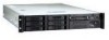
...front panel cable, 34-pin (connecting front panel board to support the Intel® Server Board SE7500WV2. The fan module and riser cards are installed for shipment, but you must be purchased separately: • Front bezel (optional) • Intel Server Board SE7500WV2 (SCSI) • Minimum of one Intel®... and one blank • Two PCI riser cards for redundancy • Other peripheral devices 7 1 Chassis Description Your Intel® SR2300 server chassis kit is designed to backplane board) • One Resource CD-ROM containing drivers, utilities, and product guide •...
...front panel cable, 34-pin (connecting front panel board to support the Intel® Server Board SE7500WV2. The fan module and riser cards are installed for shipment, but you must be purchased separately: • Front bezel (optional) • Intel Server Board SE7500WV2 (SCSI) • Minimum of one Intel®... and one blank • Two PCI riser cards for redundancy • Other peripheral devices 7 1 Chassis Description Your Intel® SR2300 server chassis kit is designed to backplane board) • One Resource CD-ROM containing drivers, utilities, and product guide •...
Product Guide
Page 8
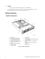
... I . PCI card bracket (full-length) K. PCI add-in card (accessory to system) F. Backplane board I J K L O M N OM14080 A. Server board (accessory to system) G. Flex bay (optional DVD/CD-ROM drive/FDD module available) M. ✏ NOTES You can install a slimline DVD drive in...encounter difficulty removing network cables connected to the card. Riser card assembly (full-length) D. Front panel board Figure 1. Control panel C. System Components 8 Intel SR2300 Chassis Subassembly Product Guide Tape drive bay (tape drive available from others) N. Power supply J. If you...
... I . PCI card bracket (full-length) K. PCI add-in card (accessory to system) F. Backplane board I J K L O M N OM14080 A. Server board (accessory to system) G. Flex bay (optional DVD/CD-ROM drive/FDD module available) M. ✏ NOTES You can install a slimline DVD drive in...encounter difficulty removing network cables connected to the card. Riser card assembly (full-length) D. Front panel board Figure 1. Control panel C. System Components 8 Intel SR2300 Chassis Subassembly Product Guide Tape drive bay (tape drive available from others) N. Power supply J. If you...

Product Guide
Page 9
Chassis Front OM14081 Chassis Description 9 Chassis Front Panel and Peripheral Bays To access the system controls and peripherals when a front bezel is installed, grasp the bezel and gently pull it towards you until it unsnaps from the chassis. Chassis handles (2) B. AB C D E F A. Drive bay (1-inch) C. Flex bay (optional DVD/CD-ROM drive/FDD module shown installed) E. Front panel indicator lights F. HDD activity/fault Indicator D. Tape drive bay (tape drive not included) Figure 2.
Chassis Front OM14081 Chassis Description 9 Chassis Front Panel and Peripheral Bays To access the system controls and peripherals when a front bezel is installed, grasp the bezel and gently pull it towards you until it unsnaps from the chassis. Chassis handles (2) B. AB C D E F A. Drive bay (1-inch) C. Flex bay (optional DVD/CD-ROM drive/FDD module shown installed) E. Front panel indicator lights F. HDD activity/fault Indicator D. Tape drive bay (tape drive not included) Figure 2.

Product Guide
Page 11
Power/sleep LED D. USB Connector J. Power button C. Fixed disk drive status LED E. ID button H. System status LED F. Reset button I OM14083 Chassis Description 11 Controls and Indicators A. NIC 2 activity LED B. ID LED G. NMI button K. AB C D EF G L KJ Figure 4. Video Connector H I . Front Panel Controls and Indicators Shown with optional DVD/CD-ROM drive/floppy disk drive installed.
Power/sleep LED D. USB Connector J. Power button C. Fixed disk drive status LED E. ID button H. System status LED F. Reset button I OM14083 Chassis Description 11 Controls and Indicators A. NIC 2 activity LED B. ID LED G. NMI button K. AB C D EF G L KJ Figure 4. Video Connector H I . Front Panel Controls and Indicators Shown with optional DVD/CD-ROM drive/floppy disk drive installed.

Product Guide
Page 12
... amber light (Note 1) indicates the system is operating normally. Blinking green light (Note 4) indicates the system is in effect at the time of servers. Continuous amber light (Note 1) indicates the system is sleeping. No light (Note 3) indicates no fixed disk drive activity nor fault (SCSI or ...blinking at the same time that the System Status LED is maintained on /off the front panel ID LED and the baseboard ID LED. Notes: 1 The Amber status takes precedence over the Green status. When the Amber LED is on from running. 12 Intel SR2300 Chassis Subassembly Product Guide
... amber light (Note 1) indicates the system is operating normally. Blinking green light (Note 4) indicates the system is in effect at the time of servers. Continuous amber light (Note 1) indicates the system is sleeping. No light (Note 3) indicates no fixed disk drive activity nor fault (SCSI or ...blinking at the same time that the System Status LED is maintained on /off the front panel ID LED and the baseboard ID LED. Notes: 1 The Amber status takes precedence over the Green status. When the Amber LED is on from running. 12 Intel SR2300 Chassis Subassembly Product Guide

Product Guide
Page 15
The bezel is now unlocked and can be monitored by server management software. Turn the lock clockwise until it stops (about a quarter turn ). Chassis Description 15 When the cover is now locked and cannot be opened again. The bezel is opened . Locking...on the front panel board, transmits a signal to the system's peripherals and control panel, install the optional front bezel, which provides a key lock. The chassis also includes a preinstalled intrusion switch for the top access cover that can be opened , the switch, located on the server board, where server management software ...
The bezel is now unlocked and can be monitored by server management software. Turn the lock clockwise until it stops (about a quarter turn ). Chassis Description 15 When the cover is now locked and cannot be opened again. The bezel is opened . Locking...on the front panel board, transmits a signal to the system's peripherals and control panel, install the optional front bezel, which provides a key lock. The chassis also includes a preinstalled intrusion switch for the top access cover that can be opened , the switch, located on the server board, where server management software ...

Product Guide
Page 20
... voltage, current and energy levels are present inside the power supply. Refer servicing of the power supply to the server before opening it. Turn off the AC power. WARNING The power button on power, telephone, and communication cables. To disconnect power... the wall outlet or the chassis. WARNING Hazardous electrical conditions may be present on the front panel DOES NOT turn off the server and disconnect the power cords, telecommunications systems, networks, and modems attached to qualified technical service personnel. 20 Intel SR2300 Chassis Subassembly Product Guide WARNING Do...
... voltage, current and energy levels are present inside the power supply. Refer servicing of the power supply to the server before opening it. Turn off the AC power. WARNING The power button on power, telephone, and communication cables. To disconnect power... the wall outlet or the chassis. WARNING Hazardous electrical conditions may be present on the front panel DOES NOT turn off the server and disconnect the power cords, telecommunications systems, networks, and modems attached to qualified technical service personnel. 20 Intel SR2300 Chassis Subassembly Product Guide WARNING Do...
Product Guide
Page 28
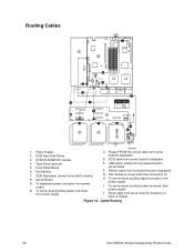
... from power supply B. Fan module to server board F. Cable Routing 28 Intel SR2300 Chassis Subassembly Product Guide DVD/CD-ROM/FDD module 4. Fan Module 7. USB ribbon cable from front panel board to server board fan connectors (2) H. To server board auxiliary power connector from server board to backplane D. Power Supply 2. Ribbon cable from server board to backplane G. SCSI cable from...
... from power supply B. Fan module to server board F. Cable Routing 28 Intel SR2300 Chassis Subassembly Product Guide DVD/CD-ROM/FDD module 4. Fan Module 7. USB ribbon cable from front panel board to server board fan connectors (2) H. To server board auxiliary power connector from server board to backplane D. Power Supply 2. Ribbon cable from server board to backplane G. SCSI cable from...

Product Guide
Page 31
... P2 HSBP P1 Serverboard FLOPPY-FP-IDECABLE ! The connector should be parallel to its board connector and not cocked to the matching connector on the server board. Route the cable to the backplane board and connect the other cable end to one side. Connect the end marked "P1-Motherboard" to... the floppy/front panel/IDE connector on the backplane. Assembling the System 31 B C A OM14584 Figure 16. If in doubt, remove, reinsert, and recheck. Install the flex ...
... P2 HSBP P1 Serverboard FLOPPY-FP-IDECABLE ! The connector should be parallel to its board connector and not cocked to the matching connector on the server board. Route the cable to the backplane board and connect the other cable end to one side. Connect the end marked "P1-Motherboard" to... the floppy/front panel/IDE connector on the backplane. Assembling the System 31 B C A OM14584 Figure 16. If in doubt, remove, reinsert, and recheck. Install the flex ...

Product Guide
Page 33
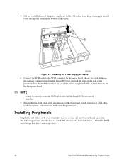
Figure 20. Connect the USB cable to the server board. Make sure the cable does not lay on top of the corner of the fan module and connect it will get damaged when you install the top cover. 2. Finish Cable Routing 1. Install the processor duct. Installing the Processor Duct OM14615 Assembling the System 33 Route the cable along the top of the backplane or it to the USB connector on the front panel.
Figure 20. Connect the USB cable to the server board. Make sure the cable does not lay on top of the corner of the fan module and connect it will get damaged when you install the top cover. 2. Finish Cable Routing 1. Install the processor duct. Installing the Processor Duct OM14615 Assembling the System 33 Route the cable along the top of the backplane or it to the USB connector on the front panel.
Product Guide
Page 34
...notch in cards, hard disk drives, a DVD/CD-ROM drive/floppy disk drive, and a tape drive. 34 Intel SR2300 Chassis Subassembly Product Guide Installing Peripherals Peripherals and add-in cards are not included in the top of the baffle. A...to install PCI add-in the bottom of the power supply air baffle, to the connector on the server board. The following sections describe how to the SCSI connector on the backplane board. ✏ NOTE It... PCI riser card is connected to the front panel board, routed over USB cable to the backplane, and connected to the matching connector. 3.
...notch in cards, hard disk drives, a DVD/CD-ROM drive/floppy disk drive, and a tape drive. 34 Intel SR2300 Chassis Subassembly Product Guide Installing Peripherals Peripherals and add-in cards are not included in the top of the baffle. A...to install PCI add-in the bottom of the power supply air baffle, to the connector on the server board. The following sections describe how to the SCSI connector on the backplane board. ✏ NOTE It... PCI riser card is connected to the front panel board, routed over USB cable to the backplane, and connected to the matching connector. 3.

Product Guide
Page 35
...have PCI cards to install, proceed to page 37, "Installing the Riser Cards on the Server Board". ✏ NOTES If you install a NIC in cards must be installed on a...guide. 2. Ensure the clip is latched. Installing a PCI Card on a Riser Card The riser card nearest the chassis sidewall (see Figure 24, A, on page 37) supports three full-length, full-height PCI add-in opening (C)..... 1. Open the retainer clip (Figure 22 or Figure 23, A) and remove the desired filler panel from the chassis. Installing a Low-Profile PCI Card in cards. Insert the edge connector of the PCI card into...
...have PCI cards to install, proceed to page 37, "Installing the Riser Cards on the Server Board". ✏ NOTES If you install a NIC in cards must be installed on a...guide. 2. Ensure the clip is latched. Installing a PCI Card on a Riser Card The riser card nearest the chassis sidewall (see Figure 24, A, on page 37) supports three full-length, full-height PCI add-in opening (C)..... 1. Open the retainer clip (Figure 22 or Figure 23, A) and remove the desired filler panel from the chassis. Installing a Low-Profile PCI Card in cards. Insert the edge connector of the PCI card into...

Product Guide
Page 40
... flex bay and slide it back until it locks in the flex bay. 1. Installing a DVD/CD-ROM drive/FDD Module OM14101 40 Intel SR2300 Chassis Subassembly Product Guide Remove the filler panel (Figure 27, A) and plug (B) from the front of the module is rotated to the down position. 3. As an accessory..., Intel offers slim-line DVD drive/FDD and CD-ROM drive/FDD modules that you feel the connectors touch. 4. Ensure the handle bar (C) on the front of the chassis. 2. Installing a DVD drive/FDD or CD-ROM drive/FDD Module Your server does not come with a DVD...
... flex bay and slide it back until it locks in the flex bay. 1. Installing a DVD/CD-ROM drive/FDD Module OM14101 40 Intel SR2300 Chassis Subassembly Product Guide Remove the filler panel (Figure 27, A) and plug (B) from the front of the module is rotated to the down position. 3. As an accessory..., Intel offers slim-line DVD drive/FDD and CD-ROM drive/FDD modules that you feel the connectors touch. 4. Ensure the handle bar (C) on the front of the chassis. 2. Installing a DVD drive/FDD or CD-ROM drive/FDD Module Your server does not come with a DVD...

Product Guide
Page 60
...-height PCI riser card. 13. Remove the cover from the chassis (C). 6. Secure the board to the board. 11. Replace the chassis cover. 60 Intel SR2300 Chassis Subassembly Product Guide Remove the front panel board from the chassis. 3. 10. Connect all hard drives and peripherals in the chassis being careful to work inside the system, observe the safety guidelines...
...-height PCI riser card. 13. Remove the cover from the chassis (C). 6. Secure the board to the board. 11. Replace the chassis cover. 60 Intel SR2300 Chassis Subassembly Product Guide Remove the front panel board from the chassis. 3. 10. Connect all hard drives and peripherals in the chassis being careful to work inside the system, observe the safety guidelines...

Product Guide
Page 71
... 480W. 2 Maximum continuous combined load for +3.3V and +5V must not exceed 115W. 3 Maximum continuous combined load for your board manual) SCSI backplane and front panel 0.40 3.5-inch drive 0.30 CD-ROM drive 0.60 3.5-inch tape drive or other peripheral 1st hot swap hard drive 2nd hot swap hard drive 3rd...
... 480W. 2 Maximum continuous combined load for +3.3V and +5V must not exceed 115W. 3 Maximum continuous combined load for your board manual) SCSI backplane and front panel 0.40 3.5-inch drive 0.30 CD-ROM drive 0.60 3.5-inch tape drive or other peripheral 1st hot swap hard drive 2nd hot swap hard drive 3rd...