
Product Specification
Page 3
... designed and tested to meet the intended thermal requirements of its published operating or non-operating limits. Intel® Entry Server Board SE7221BA1-E TPS Disclaimers Disclaimers Information in this document is provided in connection with this information. Do not finalize a design with Intel® products. This document and the software described in it is available...
... designed and tested to meet the intended thermal requirements of its published operating or non-operating limits. Intel® Entry Server Board SE7221BA1-E TPS Disclaimers Disclaimers Information in this document is provided in connection with this information. Do not finalize a design with Intel® products. This document and the software described in it is available...

Product Specification
Page 5
Intel® Entry Server Board SE7221BA1-E TPS Table of Contents 3.6.1 Advanced Configuration and Power Interface (ACPI 16 3.6.2 System States and Power States 17 3.6.3 Hardware Support 18 4. Connections and Jumper Blocks 31 6.1 Connectors ...31 6.1.1 Back Panel Connectors 31 6.1.2 Component-... PCI Express* Connectors 27 5.1.2 PCI 32...27 5.2 LAN Subsystem ...27 5.2.1 Marvell Yukon* 88E8050 Gigabit Ethernet Controller 27 5.2.2 Intel® 82551QM Integrated 10/100 LAN controller 28 5.2.3 RJ-45 LAN Connector with Integrated LEDs 28 5.2.4 Alert Standard Format (ASF)...
Intel® Entry Server Board SE7221BA1-E TPS Table of Contents 3.6.1 Advanced Configuration and Power Interface (ACPI 16 3.6.2 System States and Power States 17 3.6.3 Hardware Support 18 4. Connections and Jumper Blocks 31 6.1 Connectors ...31 6.1.1 Back Panel Connectors 31 6.1.2 Component-... PCI Express* Connectors 27 5.1.2 PCI 32...27 5.2 LAN Subsystem ...27 5.2.1 Marvell Yukon* 88E8050 Gigabit Ethernet Controller 27 5.2.2 Intel® 82551QM Integrated 10/100 LAN controller 28 5.2.3 RJ-45 LAN Connector with Integrated LEDs 28 5.2.4 Alert Standard Format (ASF)...
Product Specification
Page 8
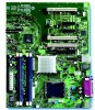
Dual Channel (Interleaved) Mode Configurations 9 Figure 4. Location of Figures Figure 1. I/O Shield ...60 Figure 19. Intel ® Server Board SE7221BA1-E Components 5 Figure 3. Dual Channel (Interleaved) Mode Configuration with Two DIMMs 9 Figure 5. Connection Diagram for Omni-directional Airflow 61 Figure 20. Dual Channel (Interleaved) Mode Configuration with Four DIMMs 10 Figure 7. Single Channel (Asymmetric) Mode Configuration with...
Dual Channel (Interleaved) Mode Configurations 9 Figure 4. Location of Figures Figure 1. I/O Shield ...60 Figure 19. Intel ® Server Board SE7221BA1-E Components 5 Figure 3. Dual Channel (Interleaved) Mode Configuration with Two DIMMs 9 Figure 5. Connection Diagram for Omni-directional Airflow 61 Figure 20. Dual Channel (Interleaved) Mode Configuration with Four DIMMs 10 Figure 7. Single Channel (Asymmetric) Mode Configuration with...

Product Specification
Page 23
...required to provide a high data transfer rates and data redundancy. Create a RAID array. 3. Revision 1.5 13 A point-to device connections, unlike Parallel ATA IDE which supports a master/slave configuration and two devices per port. Native mode is a 1 x 2-pin connector...data is used for configurations using the existing Serial ATA ports, correctly configuring the BIOS, and installing drivers. Intel® Entry Server Board SE7221BA1-E TPS Functional Architecture 3.3.2.2 Serial ATA Interfaces The ICH6-R's Serial ATA controller offers four independent Serial ATA ports with...
...required to provide a high data transfer rates and data redundancy. Create a RAID array. 3. Revision 1.5 13 A point-to device connections, unlike Parallel ATA IDE which supports a master/slave configuration and two devices per port. Native mode is a 1 x 2-pin connector...data is used for configurations using the existing Serial ATA ports, correctly configuring the BIOS, and installing drivers. Intel® Entry Server Board SE7221BA1-E TPS Functional Architecture 3.3.2.2 Serial ATA Interfaces The ICH6-R's Serial ATA controller offers four independent Serial ATA ports with...

Product Specification
Page 25
Intel® Entry Server Board SE7221BA1-E TPS Functional Architecture • Two remote thermal diode sensors for all three chassis fans, that can adjust the fan speed or switch the fans on or off as needed • SMBus interface 3.5.2 Thermal Monitoring Figure 9 shows the location of the sensors and fan connections on processor die ... fan connector Rear fan connector OM16679 Figure 9. Thermal Monitoring Revision 1.5 15 G 4 1 A 3 1 B C 4 1 D 1 3 Item A B C D E F G F E Description Remote ambient temperature sensor Thermal diode, located on the Server Board.
Intel® Entry Server Board SE7221BA1-E TPS Functional Architecture • Two remote thermal diode sensors for all three chassis fans, that can adjust the fan speed or switch the fans on or off as needed • SMBus interface 3.5.2 Thermal Monitoring Figure 9 shows the location of the sensors and fan connections on processor die ... fan connector Rear fan connector OM16679 Figure 9. Thermal Monitoring Revision 1.5 15 G 4 1 A 3 1 B C 4 1 D 1 3 Item A B C D E F G F E Description Remote ambient temperature sensor Thermal diode, located on the Server Board.

Product Specification
Page 28
...the system configuration, including add-in before power was interrupted (on or off ). Total system power is in the system. 3.6.3 Hardware Support The Intel® Entry Server Board SE7221BA1-E provides several power management hardware features, including: • Power connector • Fan connectors • LAN wake capabilities • Instantly Available PC... can adjust the fan speed or switch the fan on or off as needed. • All fan connectors have a +12 V DC connection 18 Revision 1.5 Functional Architecture Intel® Entry Server Board SE7221BA1-E TPS 1.
...the system configuration, including add-in before power was interrupted (on or off ). Total system power is in the system. 3.6.3 Hardware Support The Intel® Entry Server Board SE7221BA1-E provides several power management hardware features, including: • Power connector • Fan connectors • LAN wake capabilities • Instantly Available PC... can adjust the fan speed or switch the fan on or off as needed. • All fan connectors have a +12 V DC connection 18 Revision 1.5 Functional Architecture Intel® Entry Server Board SE7221BA1-E TPS 1.

Product Specification
Page 35
... available (through PIRQE) User available (through PIRQF) User available (through PIRQG) User available (through PIRQH) Notes: 1. PCI Conventional devices are connected between devices attached to another IRQ. 2. Intel® Entry Server Board SE7221BA1-E TPS Maps and Interrupts Table 9. Use the following information to specify their interrupt grouping: Revision 1.5 25 Interrupts IRQ System Resource NMI...
... available (through PIRQE) User available (through PIRQF) User available (through PIRQG) User available (through PIRQH) Notes: 1. PCI Conventional devices are connected between devices attached to another IRQ. 2. Intel® Entry Server Board SE7221BA1-E TPS Maps and Interrupts Table 9. Use the following information to specify their interrupt grouping: Revision 1.5 25 Interrupts IRQ System Resource NMI...

Product Specification
Page 36
...-R can connect each PIRQ line internally to one of PIRQ lines to IRQ signals in APIC mode. However, in certain interrupt-constrained situations, it is not an absolute requirement.) • INTC and INTD: Generally, a third interrupt on the board and therefore share the same interrupt. Maps and Interrupts Intel® Entry Server Board SE7221BA1-E TPS...
...-R can connect each PIRQ line internally to one of PIRQ lines to IRQ signals in APIC mode. However, in certain interrupt-constrained situations, it is not an absolute requirement.) • INTC and INTD: Generally, a third interrupt on the board and therefore share the same interrupt. Maps and Interrupts Intel® Entry Server Board SE7221BA1-E TPS...

Product Specification
Page 37
... Subsystem 5. Input Output Subsystem 5.1 PCI Subsystem 5.1.1 PCI Express* Connectors The Intel® Entry Server Board SE7221BA1-E provides the following functions: • x1 PCI Express* link • Basic 10/100/1000 Ethernet LAN connectivity • IEEE 802.1p and 802.1q support • 10/100/1000...the PCI Power Management Event (PME) mechanism defined in the PCI Power Management Specification Rev. 1.1 NOTE The Intel Server Board SE7221BA1-E features PCI Express x4 connectors, routed with the following PCI Express* connectors: • One PCI Express* x8 connector.
... Subsystem 5. Input Output Subsystem 5.1 PCI Subsystem 5.1.1 PCI Express* Connectors The Intel® Entry Server Board SE7221BA1-E provides the following functions: • x1 PCI Express* link • Basic 10/100/1000 Ethernet LAN connectivity • IEEE 802.1p and 802.1q support • 10/100/1000...the PCI Power Management Event (PME) mechanism defined in the PCI Power Management Specification Rev. 1.1 NOTE The Intel Server Board SE7221BA1-E features PCI Express x4 connectors, routed with the following PCI Express* connectors: • One PCI Express* x8 connector.

Product Specification
Page 38
...Green LED NIC 1 NIC 2 Green/Yellow LED OM16513 Figure 11. LAN Connector LED Locations 28 Revision 1.5 Input Output Subsystem Intel® Entry Server Board SE7221BA1-E TPS • Compliant to 802.3x flow control support • Jumbo frame support • TCP, IP, UDP checksum...State Power Management Support (L0s) • ASF 2.0 support 5.2.2 Intel® 82551QM Integrated 10/100 LAN controller The Intel® 8255QM Fast Ethernet controller provides the following functions: • Basic 10/100 Ethernet LAN connectivity • IEEE 802.3 10Base-T and 100Base-TX Compatible PHY ...
...Green LED NIC 1 NIC 2 Green/Yellow LED OM16513 Figure 11. LAN Connector LED Locations 28 Revision 1.5 Input Output Subsystem Intel® Entry Server Board SE7221BA1-E TPS • Compliant to 802.3x flow control support • Jumbo frame support • TCP, IP, UDP checksum...State Power Management Support (L0s) • ASF 2.0 support 5.2.2 Intel® 82551QM Integrated 10/100 LAN controller The Intel® 8255QM Fast Ethernet controller provides the following functions: • Basic 10/100 Ethernet LAN connectivity • IEEE 802.3 10Base-T and 100Base-TX Compatible PHY ...

Product Specification
Page 41
... use these connectors to power devices external to the computer, the power cable, and the external devices themselves. Back Panel Connectors Revision 1.5 31 Intel® Entry Server Board SE7221BA1-E TPS Connections and Jumper Blocks 6. Table 12 lists the colors used (when applicable). Additionally, the back panel connectors are not over -current protection: back panel...
... use these connectors to power devices external to the computer, the power cable, and the external devices themselves. Back Panel Connectors Revision 1.5 31 Intel® Entry Server Board SE7221BA1-E TPS Connections and Jumper Blocks 6. Table 12 lists the colors used (when applicable). Additionally, the back panel connectors are not over -current protection: back panel...

Product Specification
Page 42
... port 6.1.2 Component-side Connectors The following figure shows the locations of the component-side connectors of the Intel® Entry Server Board SE7221BA1-E. Intel® Entry Server Board SE7221BA1-E Component-side Connectors 32 Revision 1.5 Connections and Jumper Blocks Intel® Entry Server Board SE7221BA1-E TPS The table below lists the back panel connectors identified in the preceding figure. Figure 13...
... port 6.1.2 Component-side Connectors The following figure shows the locations of the component-side connectors of the Intel® Entry Server Board SE7221BA1-E. Intel® Entry Server Board SE7221BA1-E Component-side Connectors 32 Revision 1.5 Connections and Jumper Blocks Intel® Entry Server Board SE7221BA1-E TPS The table below lists the back panel connectors identified in the preceding figure. Figure 13...

Product Specification
Page 43
.... Serial ATA Connectors Pin Signal Name 1 Ground 2 TXP 3 TXN 4 Ground 5 RXN 6 RXP 7 Ground Revision 1.5 33 Chassis Intrusion Connector Pin Signal Name 1 Intruder 2 Ground Table 16. Intel® Entry Server Board SE7221BA1-E TPS Connections and Jumper Blocks Table 13. Front Chassis Fan and Rear Chassis Fan Connectors Pin Signal Name 1 Control 2 +12 V 3 Tach Table 14.
.... Serial ATA Connectors Pin Signal Name 1 Ground 2 TXP 3 TXN 4 Ground 5 RXN 6 RXP 7 Ground Revision 1.5 33 Chassis Intrusion Connector Pin Signal Name 1 Intruder 2 Ground Table 16. Intel® Entry Server Board SE7221BA1-E TPS Connections and Jumper Blocks Table 13. Front Chassis Fan and Rear Chassis Fan Connectors Pin Signal Name 1 Control 2 +12 V 3 Tach Table 14.

Product Specification
Page 44
... Signal Name 5Vsb Unused Unused Unused Unused Nic #1 Act. LED Cathode Key Unused Unused Unused Unused 34 Revision 1.5 LED Anode Nic #2 Act. Connections and Jumper Blocks Intel® Entry Server Board SE7221BA1-E TPS Table 18. Auxiliary Power Output Connector Pin Signal Name 1 +12 V 2 Ground 3 Ground 4 +5 V Table 19. Front Panel SSI Connector Pin 1 3 5 7 9 11 13...
... Signal Name 5Vsb Unused Unused Unused Unused Nic #1 Act. LED Cathode Key Unused Unused Unused Unused 34 Revision 1.5 LED Anode Nic #2 Act. Connections and Jumper Blocks Intel® Entry Server Board SE7221BA1-E TPS Table 18. Auxiliary Power Output Connector Pin Signal Name 1 +12 V 2 Ground 3 Ground 4 +5 V Table 19. Front Panel SSI Connector Pin 1 3 5 7 9 11 13...
Product Specification
Page 45
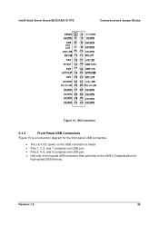
SSI Connector 6.1.3 Front Panel USB Connectors Figure 15 is a connection diagram for the front panel USB connectors. • The +5 V DC power on the USB connector is fused. • Pins 1, 3, 5, and 7 comprise one USB port. • Pins 2, 4, 6, and 8 comprise one USB port. • Use only a front panel USB connector that conforms to the USB 2.0 specification for high-speed USB devices. Intel® Entry Server Board SE7221BA1-E TPS Connections and Jumper Blocks Figure 14. Revision 1.5 35
SSI Connector 6.1.3 Front Panel USB Connectors Figure 15 is a connection diagram for the front panel USB connectors. • The +5 V DC power on the USB connector is fused. • Pins 1, 3, 5, and 7 comprise one USB port. • Pins 2, 4, 6, and 8 comprise one USB port. • Use only a front panel USB connector that conforms to the USB 2.0 specification for high-speed USB devices. Intel® Entry Server Board SE7221BA1-E TPS Connections and Jumper Blocks Figure 14. Revision 1.5 35

Product Specification
Page 46
... connector provides power directly to do so will prevent the board from booting. The board supports the use of the main power connector, leaving pins 11, 12, 23, and 24 unconnected. • ATX12V power - Table 20. Connections and Jumper Blocks Intel® Entry Server Board SE7221BA1-E TPS Power (+5 V DC) One D− USB Port D+ Ground Key (no...
... connector provides power directly to do so will prevent the board from booting. The board supports the use of the main power connector, leaving pins 11, 12, 23, and 24 unconnected. • ATX12V power - Table 20. Connections and Jumper Blocks Intel® Entry Server Board SE7221BA1-E TPS Power (+5 V DC) One D− USB Port D+ Ground Key (no...

Product Specification
Page 47
.... ⎯ The SMBus data line is powered-up to PCI Conventional bus connector 2. The 3-pin jumper blocks determine the BIOS Setup program's mode. Intel® Entry Server Board SE7221BA1-E TPS Connections and Jumper Blocks Table 21. Note the following add-in card connectors: • PCI Express* x8: one connector supporting simultaneous transfer speeds up...
.... ⎯ The SMBus data line is powered-up to PCI Conventional bus connector 2. The 3-pin jumper blocks determine the BIOS Setup program's mode. Intel® Entry Server Board SE7221BA1-E TPS Connections and Jumper Blocks Table 21. Note the following add-in card connectors: • PCI Express* x8: one connector supporting simultaneous transfer speeds up...

Product Specification
Page 48
... 1 3 Configuration The BIOS uses current configuration information and passwords for booting. After the POST runs, Setup runs automatically. During POST, the CMOS configuration is required. Connections and Jumper Blocks Intel® Entry Server Board SE7221BA1-E TPS 1 3 J6J3 Figure 16. The maintenance menu is displayed.
... 1 3 Configuration The BIOS uses current configuration information and passwords for booting. After the POST runs, Setup runs automatically. During POST, the CMOS configuration is required. Connections and Jumper Blocks Intel® Entry Server Board SE7221BA1-E TPS 1 3 J6J3 Figure 16. The maintenance menu is displayed.

Product Specification
Page 54
...Checksum Bad CMOS Settings Wrong CMOS Date/Time Not Set DMA Error FDC Failure HDC Failure Checking NVRAM..... Corresponding drive in the keyboard connection. CMOS memory may be losing power. CMOS values are invalid. These values have been corrupted. Table 27. Update OK! Memory ...bad. BIOS Error Messages Error Message GA20 Error Pri Master HDD Error Pri Slave HDD Error Pri Master Drive - System BIOS Intel® Entry Server Board SE7221BA1-E TPS 7.10 Error Messages and Beep Codes 7.10.1 BIOS Error Messages Table 27 lists the error messages and provides a ...
...Checksum Bad CMOS Settings Wrong CMOS Date/Time Not Set DMA Error FDC Failure HDC Failure Checking NVRAM..... Corresponding drive in the keyboard connection. CMOS memory may be losing power. CMOS values are invalid. These values have been corrupted. Table 27. Update OK! Memory ...bad. BIOS Error Messages Error Message GA20 Error Pri Master HDD Error Pri Slave HDD Error Pri Master Drive - System BIOS Intel® Entry Server Board SE7221BA1-E TPS 7.10 Error Messages and Beep Codes 7.10.1 BIOS Error Messages Table 27 lists the error messages and provides a ...

Product Specification
Page 61
... (average) of all PCI and PCI Express slots populated) must be connected to determine the overall system power requirements. The total +5 V current draw for add-in cards, such as follows: A fully loaded Intel® Entry Server Board SE7221BA1-E (all active components within the board that impact its power delivery subsystems. Minimum values assume a light load...
... (average) of all PCI and PCI Express slots populated) must be connected to determine the overall system power requirements. The total +5 V current draw for add-in cards, such as follows: A fully loaded Intel® Entry Server Board SE7221BA1-E (all active components within the board that impact its power delivery subsystems. Minimum values assume a light load...

