
Product Specification
Page 5
...5.3 Hardware Management Subsystem 30 5.3.1 Hardware Management 30 5.3.2 Hardware Monitoring and Fan Control ASIC 30 6. Intel® Entry Server Board SE7221BA1-E TPS Table of Contents 3.6.1 Advanced Configuration and Power Interface (ACPI 16 3.6.2 System States and Power... States 17 3.6.3 Hardware Support 18 4. Connections and Jumper Blocks 31 6.1 Connectors ...31 6.1.1 Back Panel Connectors 31 6.1.2 Component-side Connectors 32 6.1.3 Front Panel...
...5.3 Hardware Management Subsystem 30 5.3.1 Hardware Management 30 5.3.2 Hardware Monitoring and Fan Control ASIC 30 6. Intel® Entry Server Board SE7221BA1-E TPS Table of Contents 3.6.1 Advanced Configuration and Power Interface (ACPI 16 3.6.2 System States and Power... States 17 3.6.3 Hardware Support 18 4. Connections and Jumper Blocks 31 6.1 Connectors ...31 6.1.1 Back Panel Connectors 31 6.1.2 Component-side Connectors 32 6.1.3 Front Panel...
Product Specification
Page 8
... Three DIMMs 10 Figure 6. Detailed System Memory Address Map 22 Figure 11. Back Panel Connectors 31 Figure 13. Connection Diagram for Omni-directional Airflow 61 Figure 20. SSI Connector ...35 Figure 15. Block Diagram ...4 Figure 2. Intel ® Server Board SE7221BA1-E Components 5 Figure 3. Location of Figures Figure 1. Dual Channel (Interleaved) Mode Configuration with One...
... Three DIMMs 10 Figure 6. Detailed System Memory Address Map 22 Figure 11. Back Panel Connectors 31 Figure 13. Connection Diagram for Omni-directional Airflow 61 Figure 20. SSI Connector ...35 Figure 15. Block Diagram ...4 Figure 2. Intel ® Server Board SE7221BA1-E Components 5 Figure 3. Location of Figures Figure 1. Dual Channel (Interleaved) Mode Configuration with One...
Product Specification
Page 9
... 45 Table 30. Power Switch Options 17 Table 3. PCI Configuration Space Map 24 Table 9. Uncompressed INIT Code Checkpoints 45 Table 29. Intel® Entry Server Board SE7221BA1-E TPS List of Tables List of Tables Table 1. Serial ATA Connectors 33 Table 18. Auxiliary Power Output Connector 34 Table 19. BIOS... Table 11. Upper Nibble High Byte Functions 49 Revision 1.5 ix Wake-up Devices and Events 19 Table 5. DMA Channels...23 Table 8. Back Panel Connectors 32 Table 13. Main Power Connector 36 Table 21. CMOS Clear Jumper Configuration 38 Table 24.
... 45 Table 30. Power Switch Options 17 Table 3. PCI Configuration Space Map 24 Table 9. Uncompressed INIT Code Checkpoints 45 Table 29. Intel® Entry Server Board SE7221BA1-E TPS List of Tables List of Tables Table 1. Serial ATA Connectors 33 Table 18. Auxiliary Power Output Connector 34 Table 19. BIOS... Table 11. Upper Nibble High Byte Functions 49 Revision 1.5 ix Wake-up Devices and Events 19 Table 5. DMA Channels...23 Table 8. Back Panel Connectors 32 Table 13. Main Power Connector 36 Table 21. CMOS Clear Jumper Configuration 38 Table 24.

Product Specification
Page 13
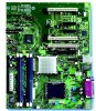
... Server Board Overview 2. Server Board Overview 2.1 Intel® Entry Server Board SE7221BA1-E SKU Availability 2.2 Intel® Entry Server Board SE7221BA1-E Feature Set The Intel® Entry Server Board SE7221BA1-E provides the following feature set: • Support for an Intel® Pentium® 4 processor in card connector with UDMA ... ATA interfaces • One Parallel ATA IDE interface with x8 throughput • Four external USB 2.0 ports on the back panel and two 2x5 USB connectors on the mother board. Each connector supports two additional USB ports for DDR2 400 MHz and DDR2...
... Server Board Overview 2. Server Board Overview 2.1 Intel® Entry Server Board SE7221BA1-E SKU Availability 2.2 Intel® Entry Server Board SE7221BA1-E Feature Set The Intel® Entry Server Board SE7221BA1-E provides the following feature set: • Support for an Intel® Pentium® 4 processor in card connector with UDMA ... ATA interfaces • One Parallel ATA IDE interface with x8 throughput • Four external USB 2.0 ports on the back panel and two 2x5 USB connectors on the mother board. Each connector supports two additional USB ports for DDR2 400 MHz and DDR2...

Product Specification
Page 22
...and the DMI interconnect. The FWH provides the nonvolatile storage of up to 66 MB/sec. Functional Architecture Intel® Entry Server Board SE7221BA1-E TPS 3.3 Intel 7221 Chipset The Intel® 7221 chipset consists of the following modes: • Programmed I/O (PIO): processor controls data ..., and uses UHCI- The drive reports the transfer rate and translation mode to two separate front panel USB connectors. 3.3.2 IDE Support The Intel® Entry Server Board SE7221BA1-E provides five IDE interface connectors: • One parallel ATA IDE connector, which supports two devices...
...and the DMI interconnect. The FWH provides the nonvolatile storage of up to 66 MB/sec. Functional Architecture Intel® Entry Server Board SE7221BA1-E TPS 3.3 Intel 7221 Chipset The Intel® 7221 chipset consists of the following modes: • Programmed I/O (PIO): processor controls data ..., and uses UHCI- The drive reports the transfer rate and translation mode to two separate front panel USB connectors. 3.3.2 IDE Support The Intel® Entry Server Board SE7221BA1-E provides five IDE interface connectors: • One parallel ATA IDE connector, which supports two devices...

Product Specification
Page 24
... and Mouse Interface PS/2 keyboard and mouse connectors are located on the back panel. 3.5 Hardware Management Subsystem The hardware management features enable the Intel® Entry Server Board SE7221BA1-E to be compatible with serialized IRQ support for PCI Conventional bus systems •... is accurate to set the parallel port mode. 3.4.3 Diskette Drive Controller The I /O controller. 3.4.1 Serial Port The Intel® Entry Server Board SE7221BA1-E has one diskette drive. The Server Board has several hardware management features, including the following features: • One ...
... and Mouse Interface PS/2 keyboard and mouse connectors are located on the back panel. 3.5 Hardware Management Subsystem The hardware management features enable the Intel® Entry Server Board SE7221BA1-E to be compatible with serialized IRQ support for PCI Conventional bus systems •... is accurate to set the parallel port mode. 3.4.3 Diskette Drive Controller The I /O controller. 3.4.1 Serial Port The Intel® Entry Server Board SE7221BA1-E has one diskette drive. The Server Board has several hardware management features, including the following features: • One ...

Product Specification
Page 26
...see Table 4. The level of ACPI with the Server Board. 3.5.4 Chassis Intrusion and Detection The Intel® Entry Server Board SE7221BA1-E supports a chassis security feature that provides full ACPI support. The use of monitoring and control ...is dependent on the hardware monitoring ASIC used with the SE7221BA1-E server board requires an operating system that detects if the chassis cover is implemented at several levels,..., and hard disk drives • Methods for a front panel power and sleep mode switch 16 Revision 1.5
...see Table 4. The level of ACPI with the Server Board. 3.5.4 Chassis Intrusion and Detection The Intel® Entry Server Board SE7221BA1-E supports a chassis security feature that provides full ACPI support. The use of monitoring and control ...is dependent on the hardware monitoring ASIC used with the SE7221BA1-E server board requires an operating system that detects if the chassis cover is implemented at several levels,..., and hard disk drives • Methods for a front panel power and sleep mode switch 16 Revision 1.5

Product Specification
Page 29
Revision 1.5 19 Table 4. Intel® Entry Server Board SE7221BA1-E TPS Functional Architecture 3.6.3.3 Wake-up Devices and Events The following table lists the devices or specific events that provides full ACPI support. NOTE The use ... wake the computer from an ACPI state requires an operating system that can wake up event from this state S1, S4, S5 (Note) Modem (back panel Serial Port A) PME# signal S1 S1, S4, S5 (Note) Power switch S1, S4, S5 PS/2 devices S1 RTC alarm S1, S4, S5 USB S1 WAKE...
Revision 1.5 19 Table 4. Intel® Entry Server Board SE7221BA1-E TPS Functional Architecture 3.6.3.3 Wake-up Devices and Events The following table lists the devices or specific events that provides full ACPI support. NOTE The use ... wake the computer from an ACPI state requires an operating system that can wake up event from this state S1, S4, S5 (Note) Modem (back panel Serial Port A) PME# signal S1 S1, S4, S5 (Note) Power switch S1, S4, S5 PS/2 devices S1 RTC alarm S1, S4, S5 USB S1 WAKE...

Product Specification
Page 41
... into two groups: • Back panel I/O connectors • Component-side I/O connectors 6.1.1 Back Panel Connectors Figure 12 shows the location of the back panel connectors. Back Panel Connectors Revision 1.5 31 A fault in the load presented by the external devices could cause damage to the computer's chassis. Intel® Entry Server Board SE7221BA1-E TPS Connections and Jumper Blocks...
... into two groups: • Back panel I/O connectors • Component-side I/O connectors 6.1.1 Back Panel Connectors Figure 12 shows the location of the back panel connectors. Back Panel Connectors Revision 1.5 31 A fault in the load presented by the external devices could cause damage to the computer's chassis. Intel® Entry Server Board SE7221BA1-E TPS Connections and Jumper Blocks...

Product Specification
Page 42
...-side Connectors 32 Revision 1.5 Figure 13. Table 12. Connections and Jumper Blocks Intel® Entry Server Board SE7221BA1-E TPS The table below lists the back panel connectors identified in the preceding figure. Back Panel Connectors Back Panel Connectors A B C D E F G H Description PS/2 mouse port [Green] PS/2 keyboard port [Purple] Serial port A [Teal] Parallel port [Burgundy] PCI Express...
...-side Connectors 32 Revision 1.5 Figure 13. Table 12. Connections and Jumper Blocks Intel® Entry Server Board SE7221BA1-E TPS The table below lists the back panel connectors identified in the preceding figure. Back Panel Connectors Back Panel Connectors A B C D E F G H Description PS/2 mouse port [Green] PS/2 keyboard port [Purple] Serial port A [Teal] Parallel port [Burgundy] PCI Express...

Product Specification
Page 44
Front Panel SSI Connector Pin 1 3 5 7 9 11 13 15 17 19 21 23 25 27 29 31 33 Signal Name Power LED Anode Key Power LED Cathode HDD ... 32 34 Signal Name 5Vsb Unused Unused Unused Unused Nic #1 Act. LED Anode Nic #1 Act. LED Anode HDD Act. Connections and Jumper Blocks Intel® Entry Server Board SE7221BA1-E TPS Table 18. LED Cathode SMBus SDA SMBus SCL Chassis Intrusion Nic #2 Act. LED Cathode Key Unused Unused Unused Unused 34 Revision 1.5 Auxiliary...
Front Panel SSI Connector Pin 1 3 5 7 9 11 13 15 17 19 21 23 25 27 29 31 33 Signal Name Power LED Anode Key Power LED Cathode HDD ... 32 34 Signal Name 5Vsb Unused Unused Unused Unused Nic #1 Act. LED Anode Nic #1 Act. LED Anode HDD Act. Connections and Jumper Blocks Intel® Entry Server Board SE7221BA1-E TPS Table 18. LED Cathode SMBus SDA SMBus SCL Chassis Intrusion Nic #2 Act. LED Cathode Key Unused Unused Unused Unused 34 Revision 1.5 Auxiliary...
Product Specification
Page 45
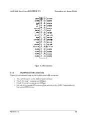
SSI Connector 6.1.3 Front Panel USB Connectors Figure 15 is a connection diagram for the front panel USB connectors. • The +5 V DC power on the USB connector is fused. • Pins 1, 3, 5, and 7 comprise one USB port. • Pins 2, 4, 6, and 8 comprise one USB port. • Use only a front panel USB connector that conforms to the USB 2.0 specification for high-speed USB devices. Intel® Entry Server Board SE7221BA1-E TPS Connections and Jumper Blocks Figure 14. Revision 1.5 35
SSI Connector 6.1.3 Front Panel USB Connectors Figure 15 is a connection diagram for the front panel USB connectors. • The +5 V DC power on the USB connector is fused. • Pins 1, 3, 5, and 7 comprise one USB port. • Pins 2, 4, 6, and 8 comprise one USB port. • Use only a front panel USB connector that conforms to the USB 2.0 specification for high-speed USB devices. Intel® Entry Server Board SE7221BA1-E TPS Connections and Jumper Blocks Figure 14. Revision 1.5 35

Product Specification
Page 46
... on the right most pins of ATX12V or EPS 12V power supplies with 2 x 10 connectors previously used . Table 20. Connections and Jumper Blocks Intel® Entry Server Board SE7221BA1-E TPS Power (+5 V DC) One D− USB Port D+ Ground Key (no pin) 1 2 3 4 5 6 7 8 10 Power (+5 V DC) D− One USB D+...) 17 Ground 18 Ground 19 Ground 20 No connect 21 +5 V 22 +5 V 23 +5 V 24 Ground 36 Revision 1.5 Connection Diagram for Front Panel USB Connectors 6.1.4 Power Supply Connectors The board has three power supply connectors: • Main power -
... on the right most pins of ATX12V or EPS 12V power supplies with 2 x 10 connectors previously used . Table 20. Connections and Jumper Blocks Intel® Entry Server Board SE7221BA1-E TPS Power (+5 V DC) One D− USB Port D+ Ground Key (no pin) 1 2 3 4 5 6 7 8 10 Power (+5 V DC) D− One USB D+...) 17 Ground 18 Ground 19 Ground 20 No connect 21 +5 V 22 +5 V 23 +5 V 24 Ground 36 Revision 1.5 Connection Diagram for Front Panel USB Connectors 6.1.4 Power Supply Connectors The board has three power supply connectors: • Main power -

Product Specification
Page 61
... V +12 V -12 V +5 VSB Server Board 1.2A 2.6A 0.00 0.05A 1.0A Processor 15A Memory DIMMs 6A Fans Processor Fan * 1A Front Panel Fan 0.8A Rear Panel Fan 0.8A Aux Fan 0.8A Keyboard/Mouse 345mA PCI Slots (3) 7.6A 5A 3.75mA PCIe Slots x4 Slots (2) ** 3A 0.5A x8 Slot (1) *** 3A... particular processor speed. Use the datasheets for add-in boards for add-in cards, such as follows: A fully loaded Intel® Entry Server Board SE7221BA1-E (all active components within the board that impact its power delivery subsystems. Minimum values assume a light load placed on ...
... V +12 V -12 V +5 VSB Server Board 1.2A 2.6A 0.00 0.05A 1.0A Processor 15A Memory DIMMs 6A Fans Processor Fan * 1A Front Panel Fan 0.8A Rear Panel Fan 0.8A Aux Fan 0.8A Keyboard/Mouse 345mA PCI Slots (3) 7.6A 5A 3.75mA PCIe Slots x4 Slots (2) ** 3A 0.5A x8 Slot (1) *** 3A... particular processor speed. Use the datasheets for add-in boards for add-in cards, such as follows: A fully loaded Intel® Entry Server Board SE7221BA1-E (all active components within the board that impact its power delivery subsystems. Minimum values assume a light load placed on ...


