Product Guide
Page 5
...Board Features Supported Operating Systems 10 Desktop Board Components 11 Processor ...13 Main Memory...13 Chipset...14 Graphics Subsystem 14 Audio Subsystem 14 Input/Output (I/O) Controller 15 LAN Subsystem 15 LAN Subsystem Software 16 RJ-45 LAN Connector LEDs 16 Hi-Speed USB 2.0 Support 17 Enhanced ...IDE Interface 17 Serial ATA...17 Expandability...17 BIOS ...17 IDE Auto Configuration 18 PCI Auto Configuration 18 Security Passwords 18...
...Board Features Supported Operating Systems 10 Desktop Board Components 11 Processor ...13 Main Memory...13 Chipset...14 Graphics Subsystem 14 Audio Subsystem 14 Input/Output (I/O) Controller 15 LAN Subsystem 15 LAN Subsystem Software 16 RJ-45 LAN Connector LEDs 16 Hi-Speed USB 2.0 Support 17 Enhanced ...IDE Interface 17 Serial ATA...17 Expandability...17 BIOS ...17 IDE Auto Configuration 18 PCI Auto Configuration 18 Security Passwords 18...
Product Guide
Page 9
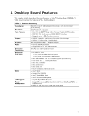
Feature Summary Form Factor Processor Mini-ITX (171.45 millimeters [6.75 inches] x 171.45 millimeters [6.75 inches]) Intel® Celeron® processor Main Memory • One 240-pin SDRAM Dual Inline Memory Module (DIMM) socket • 533/400 MHz single channel DDR2 SDRAM interface • Supports up to 1 GB of system memory Chipset • SiS662* Graphics and...
Feature Summary Form Factor Processor Mini-ITX (171.45 millimeters [6.75 inches] x 171.45 millimeters [6.75 inches]) Intel® Celeron® processor Main Memory • One 240-pin SDRAM Dual Inline Memory Module (DIMM) socket • 533/400 MHz single channel DDR2 SDRAM interface • Supports up to 1 GB of system memory Chipset • SiS662* Graphics and...
Product Guide
Page 12
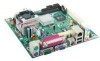
... (2 x 2) Main power connector (2 x 10) Processor DDR 2 DIMM connector IDE connector Serial ATA connectors Front panel header Battery BIOS configuration jumper Related Links: Go to the following links for more information about: • Desktop Board D201GLY2 • Audio software and utilities • LAN software and drivers http://www.intel.com/design/motherbd http://support...
... (2 x 2) Main power connector (2 x 10) Processor DDR 2 DIMM connector IDE connector Serial ATA connectors Front panel header Battery BIOS configuration jumper Related Links: Go to the following links for more information about: • Desktop Board D201GLY2 • Audio software and utilities • LAN software and drivers http://www.intel.com/design/motherbd http://support...
Product Guide
Page 13
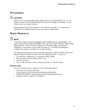
... DIMMs • Serial Presence Detect (SPD) memory only • Non-ECC memory • Up to 1 GB of system memory utilizing 512 Mb or 1 Gb technology Related Links: Go to the board, or the system may result in damage to the following links or pages for normal ...operation. Main Memory NOTE To be fully compliant with all applicable Intel® SDRAM memory specifications, the board should be populated with gold-plated contacts. Desktop Board D201GLY2 includes an Intel Celeron processor. The processor is soldered to this effect on the screen at power up. The Desktop...
... DIMMs • Serial Presence Detect (SPD) memory only • Non-ECC memory • Up to 1 GB of system memory utilizing 512 Mb or 1 Gb technology Related Links: Go to the board, or the system may result in damage to the following links or pages for normal ...operation. Main Memory NOTE To be fully compliant with all applicable Intel® SDRAM memory specifications, the board should be populated with gold-plated contacts. Desktop Board D201GLY2 includes an Intel Celeron processor. The processor is soldered to this effect on the screen at power up. The Desktop...
Product Guide
Page 17
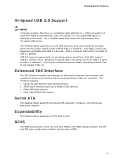
...transfer rates. Expandability The Desktop Board supports one device per channel. Enhanced IDE Interface The IDE interface handles the exchange of information between the processor and peripheral devices such as CD-ROM or DVD drives) • Older PIO Mode devices • Ultra DMA-33/66/100 modes ...panel and four ports routed to USB 1.1 operation. BIOS The BIOS provides the Power-On Self-Test (POST), the BIOS Setup program, the PCI and IDE auto-configuration utilities, and the video BIOS. 17 USB 2.0 support requires both an operating system and drivers that do not support ...
...transfer rates. Expandability The Desktop Board supports one device per channel. Enhanced IDE Interface The IDE interface handles the exchange of information between the processor and peripheral devices such as CD-ROM or DVD drives) • Older PIO Mode devices • Ultra DMA-33/66/100 modes ...panel and four ports routed to USB 1.1 operation. BIOS The BIOS provides the Power-On Self-Test (POST), the BIOS Setup program, the PCI and IDE auto-configuration utilities, and the video BIOS. 17 USB 2.0 support requires both an operating system and drivers that do not support ...
Product Guide
Page 19
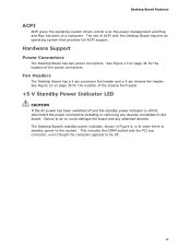
...Board has two power connectors. See Figure 12 on page 36 for the location of the power connectors. Fan Headers The Desktop Board has a 3-pin processor fan header and a 3-pin chassis fan header. The Desktop Board's standby power indicator, shown in Figure 4, is lit when there is standby power to...off . 19 Failure to do so could damage the board and any devices connected to the board. This includes the DIMM socket and the PCI bus connector, even though the computer appears to the system. Desktop Board Features ACPI ACPI gives the operating system direct control over the power ...
...Board has two power connectors. See Figure 12 on page 36 for the location of the power connectors. Fan Headers The Desktop Board has a 3-pin processor fan header and a 3-pin chassis fan header. The Desktop Board's standby power indicator, shown in Figure 4, is lit when there is standby power to...off . 19 Failure to do so could damage the board and any devices connected to the board. This includes the DIMM socket and the PCI bus connector, even though the computer appears to the system. Desktop Board Features ACPI ACPI gives the operating system direct control over the power ...

Product Guide
Page 24
... D201GLY2 Product Guide Installation Precautions When you install and test the Intel Desktop Board, observe all warnings and cautions that could cause a short circuit Observe all warnings and cautions in this section and the instructions supplied with... pins on connectors or headers • Sharp pins on printed circuit assemblies • Rough edges and sharp corners on the chassis • Hot components (like processors, voltage regulators, and heat sinks) • Damage to wires that instruct you increase safety risk and the possibility of noncompliance with the chassis and associated...
... D201GLY2 Product Guide Installation Precautions When you install and test the Intel Desktop Board, observe all warnings and cautions that could cause a short circuit Observe all warnings and cautions in this section and the instructions supplied with... pins on connectors or headers • Sharp pins on printed circuit assemblies • Rough edges and sharp corners on the chassis • Hot components (like processors, voltage regulators, and heat sinks) • Damage to wires that instruct you increase safety risk and the possibility of noncompliance with the chassis and associated...
Product Guide
Page 36
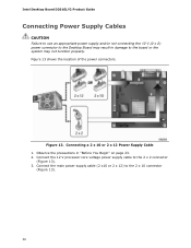
... cable (2 x10 or 2 x 12) to the 2 x 2 connector (Figure 13). 3. Figure 13 shows the location of the power connectors. Connect the 12 V processor core voltage power supply cable to the 2 x 10 connector (Figure 13). 36 Observe the precautions in damage to the board or the system may not... function properly. Figure 13. Intel Desktop Board D201GLY2 Product Guide Connecting Power Supply Cables CAUTION Failure to use an appropriate power supply and/or not connecting the 12 V (2 x 2)...
... cable (2 x10 or 2 x 12) to the 2 x 2 connector (Figure 13). 3. Figure 13 shows the location of the power connectors. Connect the 12 V processor core voltage power supply cable to the 2 x 10 connector (Figure 13). 36 Observe the precautions in damage to the board or the system may not... function properly. Figure 13. Intel Desktop Board D201GLY2 Product Guide Connecting Power Supply Cables CAUTION Failure to use an appropriate power supply and/or not connecting the 12 V (2 x 2)...
Product Guide
Page 47
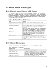
...BIOS update is powered on, and blinks off for 0.5 second; The CMOS memory may be bad. Front-panel Power LED Blink Codes Type Processor initialization complete POST complete BIOS update in progress Pattern On when system powers up, then off for 0.5 second On when system powers up, then... off for 0.5 second Off when update begins, then on for 0.5 second, then off for 0.5 second when processor initialization is powered off Thermal warning On-off (0.5 second each ) two times, then 3.0 second pause (off) between on-off blink pattern; Table 10....
...BIOS update is powered on, and blinks off for 0.5 second; The CMOS memory may be bad. Front-panel Power LED Blink Codes Type Processor initialization complete POST complete BIOS update in progress Pattern On when system powers up, then off for 0.5 second On when system powers up, then... off for 0.5 second Off when update begins, then on for 0.5 second, then off for 0.5 second when processor initialization is powered off Thermal warning On-off (0.5 second each ) two times, then 3.0 second pause (off) between on-off blink pattern; Table 10....


