
Product Specification
Page 6
...58 3.3.2 PCI IDE Support 59 3.4 System Management BIOS (SMBIOS 59 3.5 Legacy USB Support 60 3.6 BIOS Updates 61 3.6.1 Language Support 61 3.6.2 Custom Splash Screen 61 3.7 BIOS Recovery 62 3.8 Boot Options 62 3.8.1 CD-ROM Boot 62 3.8.2 Network Boot 62 3.8.3 Booting Without Attached Devices 63 3.8.4 Changing the Default Boot Device During POST 63 3.9 Adjusting Boot Speed 63 3.9.1 Peripheral Selection and Configuration 63 3.9.2 BIOS Boot Optimizations 64 3.10 BIOS Security Features 64 4 Error Messages and Beep Codes 4.1 Speaker 67 4.2 BIOS Beep Codes 67 4.3 BIOS Error Messages...
...58 3.3.2 PCI IDE Support 59 3.4 System Management BIOS (SMBIOS 59 3.5 Legacy USB Support 60 3.6 BIOS Updates 61 3.6.1 Language Support 61 3.6.2 Custom Splash Screen 61 3.7 BIOS Recovery 62 3.8 Boot Options 62 3.8.1 CD-ROM Boot 62 3.8.2 Network Boot 62 3.8.3 Booting Without Attached Devices 63 3.8.4 Changing the Default Boot Device During POST 63 3.9 Adjusting Boot Speed 63 3.9.1 Peripheral Selection and Configuration 63 3.9.2 BIOS Boot Optimizations 64 3.10 BIOS Security Features 64 4 Error Messages and Beep Codes 4.1 Speaker 67 4.2 BIOS Beep Codes 67 4.3 BIOS Error Messages...
Product Specification
Page 7
... Rear Chassis (3-Pin) Fan Headers 46 18. Main Power Connector 47 22. Back Panel Audio Connector Options 25 5. Location of the Standby Power Indicator LED 38 9. Connection Diagram for Front Panel Header 48 13. Feature Summary 10 2. LAN Connector LED States 27 6. Intel AMT States 36 10. System Memory Map 41 11. Processor Core Power Connector 47 21. Major Board Components 12 2. Thermal Sensors and Fan Headers 31 7. Supported Memory Configurations 17 4. Block Diagram 14 3. Memory Channel and DIMM Configuration 18 4. Location of the Intel AMT...
... Rear Chassis (3-Pin) Fan Headers 46 18. Main Power Connector 47 22. Back Panel Audio Connector Options 25 5. Location of the Standby Power Indicator LED 38 9. Connection Diagram for Front Panel Header 48 13. Feature Summary 10 2. LAN Connector LED States 27 6. Intel AMT States 36 10. System Memory Map 41 11. Processor Core Power Connector 47 21. Major Board Components 12 2. Thermal Sensors and Fan Headers 31 7. Supported Memory Configurations 17 4. Block Diagram 14 3. Memory Channel and DIMM Configuration 18 4. Location of the Intel AMT...
Product Specification
Page 15
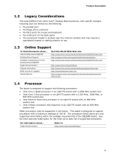
... ... Intel Desktop Board DQ35MP Desktop Board Support Available configurations for the Desktop Board DQ35MP Supported processors Chipset information BIOS and driver updates Tested Memory Visit this World Wide Web site: http://www.intel.com/products/motherboard/DQ35MP/index.htm http://support.intel.com/support/motherboards/desktop http://www.intel.com/products/motherboard/DQ35MP/index.htm http://www.intel.com/go /findcpu 15 See the Intel web site listed below for mouse and keyboard • No serial port on the back panel • The serial port header is located near the memory sockets...
... ... Intel Desktop Board DQ35MP Desktop Board Support Available configurations for the Desktop Board DQ35MP Supported processors Chipset information BIOS and driver updates Tested Memory Visit this World Wide Web site: http://www.intel.com/products/motherboard/DQ35MP/index.htm http://support.intel.com/support/motherboards/desktop http://www.intel.com/products/motherboard/DQ35MP/index.htm http://www.intel.com/go /findcpu 15 See the Intel web site listed below for mouse and keyboard • No serial port on the back panel • The serial port header is located near the memory sockets...
Product Specification
Page 24
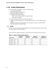
... No Yes Back panel - Intel Desktop Board DQ35MP Technical Product Specification 1.10 Audio Subsystem The onboard audio subsystem consists of the following: • Intel 82801IDO ICH9DO • RealTek ALC268-GR audio codec • Back panel audio connectors • Component-side audio headers: ⎯ Intel® High Definition Audio front panel header ⎯ HD Audio Link header The audio subsystem supports the following features: • A signal-to obtain Microsoft Windows Vista certification. Audio Jack Retasking Support Audio Jack Supports Line in...
... No Yes Back panel - Intel Desktop Board DQ35MP Technical Product Specification 1.10 Audio Subsystem The onboard audio subsystem consists of the following: • Intel 82801IDO ICH9DO • RealTek ALC268-GR audio codec • Back panel audio connectors • Component-side audio headers: ⎯ Intel® High Definition Audio front panel header ⎯ HD Audio Link header The audio subsystem supports the following features: • A signal-to obtain Microsoft Windows Vista certification. Audio Jack Retasking Support Audio Jack Supports Line in...
Product Specification
Page 57
... Management BIOS (SMBIOS 59 3.5 Legacy USB Support 60 3.6 BIOS Updates 61 3.7 BIOS Recovery 62 3.8 Boot Options 62 3.9 Adjusting Boot Speed 63 3.10 BIOS Security Features 64 3.1 Introduction The board uses an Intel BIOS that is stored in configure mode. 3 Overview of BIOS and a revision code. Maintenance Main Advanced Security Power Boot Intel ME Exit NOTE The maintenance menu is displayed only when the board is in the Serial Peripheral Interface Flash Memory (SPI Flash) and can be updated using a disk-based program. When the BIOS Setup configuration jumper is powered...
... Management BIOS (SMBIOS 59 3.5 Legacy USB Support 60 3.6 BIOS Updates 61 3.7 BIOS Recovery 62 3.8 Boot Options 62 3.9 Adjusting Boot Speed 63 3.10 BIOS Security Features 64 3.1 Introduction The board uses an Intel BIOS that is stored in configure mode. 3 Overview of BIOS and a revision code. Maintenance Main Advanced Security Power Boot Intel ME Exit NOTE The maintenance menu is displayed only when the board is in the Serial Peripheral Interface Flash Memory (SPI Flash) and can be updated using a disk-based program. When the BIOS Setup configuration jumper is powered...
Product Specification
Page 59
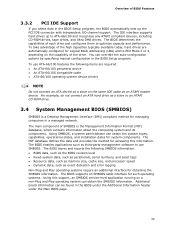
.../100 compatible cable • ATA-66/100 operating system device drivers NOTE Do not connect an ATA device as a slave on a non-Plug and Play operating system can override the auto-configuration options by specifying manual configuration in the BIOS under the Additional Information header under the Main BIOS page. 59 The BIOS stores and reports the following items are automatically configured for system components. Overview of BIOS Features 3.3.2 PCI IDE Support...
.../100 compatible cable • ATA-66/100 operating system device drivers NOTE Do not connect an ATA device as a slave on a non-Plug and Play operating system can override the auto-configuration options by specifying manual configuration in the BIOS under the Additional Information header under the Main BIOS page. 59 The BIOS stores and reports the following items are automatically configured for system components. Overview of BIOS Features 3.3.2 PCI IDE Support...
Product Specification
Page 62
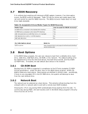
... enabled, the last default boot device is the network. 3.8.1 CD-ROM Boot Booting from CD-ROM is supported in compliance to boot from the onboard LAN or a network add-in card with a 1.44 MB diskette) No USB hard disk drive No For information about BIOS recovery Refer to http://support.intel.com/support/motherboards/desktop/ sb/CS-022312.htm 3.8 Boot Options In the BIOS Setup program, the user can choose to the El Torito bootable CD-ROM format specification. Pressing the key during POST, the User Access...
... enabled, the last default boot device is the network. 3.8.1 CD-ROM Boot Booting from CD-ROM is supported in compliance to boot from the onboard LAN or a network add-in card with a 1.44 MB diskette) No USB hard disk drive No For information about BIOS recovery Refer to http://support.intel.com/support/motherboards/desktop/ sb/CS-022312.htm 3.8 Boot Options In the BIOS Setup program, the user can choose to the El Torito bootable CD-ROM format specification. Pressing the key during POST, the User Access...
Product Specification
Page 64
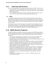
... LAN device if it is set, pressing the key at all the Setup options in the BIOS Setup program. Users have access to Setup respective to boot the computer. • For enhanced security, use different passwords for a password. A supervisor password and a user password can enter either the supervisor password or the user password to view and change all . If only the supervisor password is entered. • Setting the user password restricts who can boot the computer. Intel Desktop Board DQ35MP Technical Product Specification 3.9.2 BIOS Boot Optimizations Use...
... LAN device if it is set, pressing the key at all the Setup options in the BIOS Setup program. Users have access to Setup respective to boot the computer. • For enhanced security, use different passwords for a password. A supervisor password and a user password can enter either the supervisor password or the user password to view and change all . If only the supervisor password is entered. • Setting the user password restricts who can boot the computer. Intel Desktop Board DQ35MP Technical Product Specification 3.9.2 BIOS Boot Optimizations Use...
Product Specification
Page 69
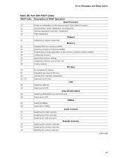
... Hot Plug PCI controller initialization 53 - 57 Reserved for PCI Bus USB 58 Resetting USB bus 59 Reserved for USB ATA/ATAPI/SATA 5A Resetting PATA/SATA bus and all devices 5B Reserved for ATA SMBus 5C Resetting SMBus 5D Reserved for SMBus Local Console 70 Resetting the VGA controller 71 Disabling the VGA controller 72 Enabling the VGA controller Remote Console 78 Resetting the console controller 79 Disabling the console controller 7A Enabling the console controller continued 69 Error Messages and Beep Codes...
... Hot Plug PCI controller initialization 53 - 57 Reserved for PCI Bus USB 58 Resetting USB bus 59 Reserved for USB ATA/ATAPI/SATA 5A Resetting PATA/SATA bus and all devices 5B Reserved for ATA SMBus 5C Resetting SMBus 5D Reserved for SMBus Local Console 70 Resetting the VGA controller 71 Disabling the VGA controller 72 Enabling the VGA controller Remote Console 78 Resetting the console controller 79 Disabling the console controller 7A Enabling the console controller continued 69 Error Messages and Beep Codes...
Product Specification
Page 71
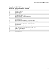
Error Messages and Beep Codes Table 38. Port 80h POST Codes (continued) POST Code Description of POST Operation DXE Drivers E7 Waiting for user input E8 Checking password E9 Entering BIOS setup EB Calling Legacy Option ROMs Runtime Phase/EFI operating system boot F4 Entering Sleep state F5 Exiting Sleep state F8 EFI boot service ExitBootServices ( ) has been called F9 EFI runtime service SetVirtualAddressMap ( ) has been called FA EFI runtime service ResetSystem ( ) has been called PEIMs/Recovery 30...
Error Messages and Beep Codes Table 38. Port 80h POST Codes (continued) POST Code Description of POST Operation DXE Drivers E7 Waiting for user input E8 Checking password E9 Entering BIOS setup EB Calling Legacy Option ROMs Runtime Phase/EFI operating system boot F4 Entering Sleep state F5 Exiting Sleep state F8 EFI boot service ExitBootServices ( ) has been called F9 EFI runtime service SetVirtualAddressMap ( ) has been called FA EFI runtime service ResetSystem ( ) has been called PEIMs/Recovery 30...
Product Guide
Page 3
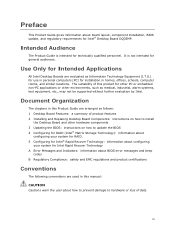
... not be supported without further evaluation by Intel. Use Only for Intended Applications All Intel Desktop Boards are used in this Product Guide are arranged as follows: 1 Desktop Board Features: a summary of product features 2 Installing and Replacing Desktop Board Components: instructions on how to update the BIOS 4 Configuring for RAID (Intel® Matrix Storage Technology): information about configuring your system for RAID. 5 Configuring for Intel® Rapid Recover Technology: information about configuring your system for Intel® Desktop Board DQ35MP. Document Organization...
... not be supported without further evaluation by Intel. Use Only for Intended Applications All Intel Desktop Boards are used in this Product Guide are arranged as follows: 1 Desktop Board Features: a summary of product features 2 Installing and Replacing Desktop Board Components: instructions on how to update the BIOS 4 Configuring for RAID (Intel® Matrix Storage Technology): information about configuring your system for RAID. 5 Configuring for Intel® Rapid Recover Technology: information about configuring your system for Intel® Desktop Board DQ35MP. Document Organization...

Product Guide
Page 7
... 4. Connecting the Processor Fan Heat Sink Cable to the Processor Fan Header ..........39 14. Use DDR2 DIMMs 43 18. Contents 4 Configuring for RAID (Intel® Matrix Storage Technology) Configuring the BIOS for Intel Matrix Storage Technology 71 Creating Your RAID Set 71 Loading the Intel Matrix Storage Technology RAID Drivers and Software 72 Setting Up a "RAID Ready" System 72 5 Configuring for Intel® Rapid Recover Technology Enabling Intel Rapid Recover Technology 73 Creating a Recovery Volume 74 Creating a Recovery Volume Using the RAID Option ROM 74 Creating a Recovery...
... 4. Connecting the Processor Fan Heat Sink Cable to the Processor Fan Header ..........39 14. Use DDR2 DIMMs 43 18. Contents 4 Configuring for RAID (Intel® Matrix Storage Technology) Configuring the BIOS for Intel Matrix Storage Technology 71 Creating Your RAID Set 71 Loading the Intel Matrix Storage Technology RAID Drivers and Software 72 Setting Up a "RAID Ready" System 72 5 Configuring for Intel® Rapid Recover Technology Enabling Intel Rapid Recover Technology 73 Creating a Recovery Volume 74 Creating a Recovery Volume Using the RAID Option ROM 74 Creating a Recovery...
Product Guide
Page 22
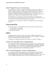
... recovery drive to run the BIOS Setup program after you can be updated by specifying manual configuration in the BIOS Setup program. You do not need to be recovered. Intel Desktop Board DQ35MP Product Guide Intel® Rapid Recover Technology Intel Rapid Recover Technology enables fast and easy recovery of your primary or master drive onto a second hard drive, the recovery drive. Serial ATA and IDE Auto Configuration If you install a Serial ATA or IDE device (such as a read-only volume so you install a PCI/PCI Express...
... recovery drive to run the BIOS Setup program after you can be updated by specifying manual configuration in the BIOS Setup program. You do not need to be recovered. Intel Desktop Board DQ35MP Product Guide Intel® Rapid Recover Technology Intel Rapid Recover Technology enables fast and easy recovery of your primary or master drive onto a second hard drive, the recovery drive. Serial ATA and IDE Auto Configuration If you install a Serial ATA or IDE device (such as a read-only volume so you install a PCI/PCI Express...
Product Guide
Page 23
... be used to access Setup. Valid passwords are set , you must enter either password to view and change all Setup options. Hard Disk Drive Passwords The hard disk drive password security feature will not lock the drive, but do not interact with the following restrictions: • The supervisor password gives unrestricted access to boot the computer. Passwords are between two and eight characters. There are then available for a hard disk drive password. For instructions on resetting the password, see Clearing BIOS Security Passwords...
... be used to access Setup. Valid passwords are set , you must enter either password to view and change all Setup options. Hard Disk Drive Passwords The hard disk drive password security feature will not lock the drive, but do not interact with the following restrictions: • The supervisor password gives unrestricted access to boot the computer. Passwords are between two and eight characters. There are then available for a hard disk drive password. For instructions on resetting the password, see Clearing BIOS Security Passwords...
Product Guide
Page 31
...continue to operate even though the front panel power button is not available, you how to: • Install the I/O shield • Install and remove the Desktop Board • Install and remove a processor • Install and remove memory • Install and remove a PCI Express x16 card • Connect the IDE and Serial ATA cables • Connect to the internal headers • Connect to the audio system • Connect chassis fan and power supply cables • Set the BIOS configuration jumper • Clear passwords • Replace the battery Before You Begin CAUTIONS The procedures...
...continue to operate even though the front panel power button is not available, you how to: • Install the I/O shield • Install and remove the Desktop Board • Install and remove a processor • Install and remove memory • Install and remove a PCI Express x16 card • Connect the IDE and Serial ATA cables • Connect to the internal headers • Connect to the audio system • Connect chassis fan and power supply cables • Set the BIOS configuration jumper • Clear passwords • Replace the battery Before You Begin CAUTIONS The procedures...
Product Guide
Page 55
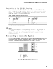
... the Intel Express Installer DVD-ROM, the multi-channel audio feature can be enabled. Item Description A Audio line in B Audio line out C Mic in the table. Each USB header can be used to connect two USB devices. Use a shielded cable that have an unshielded cable attached to a USB port might not meet FCC Class B requirements, even if no device or a low-speed USB device is attached to the cable. Table 11. USB 2.0 Header Signal Names USB Port A Pin Signal Name Pin 1 Power (+5 V) 2 3 D- 4 5 D+ 6 7 Ground 8 9 Key...
... the Intel Express Installer DVD-ROM, the multi-channel audio feature can be enabled. Item Description A Audio line in B Audio line out C Mic in the table. Each USB header can be used to connect two USB devices. Use a shielded cable that have an unshielded cable attached to a USB port might not meet FCC Class B requirements, even if no device or a low-speed USB device is attached to the cable. Table 11. USB 2.0 Header Signal Names USB Port A Pin Signal Name Pin 1 Power (+5 V) 2 3 D- 4 5 D+ 6 7 Ground 8 9 Key...
Product Guide
Page 56
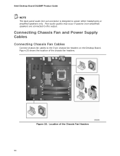
Figure 25. Intel Desktop Board DQ35MP Product Guide NOTE The back panel audio line out connector is designed to the 3-pin chassis fan headers on the Desktop Board. Connecting Chassis Fan and Power Supply Cables Connecting Chassis Fan Cables Connect chassis fan cables to power either headphones or amplified speakers only. Location of the chassis fan headers. Figure 25 shows the location of the Chassis Fan Headers 56 Poor audio quality may occur if passive (non-amplified) speakers are connected to this output.
Figure 25. Intel Desktop Board DQ35MP Product Guide NOTE The back panel audio line out connector is designed to the 3-pin chassis fan headers on the Desktop Board. Connecting Chassis Fan and Power Supply Cables Connecting Chassis Fan Cables Connect chassis fan cables to power either headphones or amplified speakers only. Location of the chassis fan headers. Figure 25 shows the location of the Chassis Fan Headers 56 Poor audio quality may occur if passive (non-amplified) speakers are connected to this output.
Product Guide
Page 60
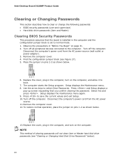
... configuration jumper block (see "Clearing or Changing Hard Disk Drive Passwords" below . 6. Setup displays the Maintenance menu. 8. Turn off all peripheral devices connected to the computer. Turn off the computer. Remove the computer cover. 4. Disconnect the computer's power cord from the AC power source (wall outlet or power adapter). 3. Turn off the computer. Press to select Clear Passwords. Select Yes and press . Intel Desktop Board DQ35MP Product Guide Clearing or Changing Passwords This section describes how to clear or change the following passwords...
... configuration jumper block (see "Clearing or Changing Hard Disk Drive Passwords" below . 6. Setup displays the Maintenance menu. 8. Turn off all peripheral devices connected to the computer. Turn off the computer. Remove the computer cover. 4. Disconnect the computer's power cord from the AC power source (wall outlet or power adapter). 3. Turn off the computer. Press to select Clear Passwords. Select Yes and press . Intel Desktop Board DQ35MP Product Guide Clearing or Changing Passwords This section describes how to clear or change the following passwords...

Product Guide
Page 72
Install the Intel® ICH9 SATA RAID Controller driver. Click on the "Load Drivers" option and insert the Intel Express Installer CD/DVD into your desktop board or after downloading it from this section: "Configuring the BIOS for Intel Matrix Storage Technology" and "Loading the Intel Matrix Storage Technology RAID Drivers and Software". Setting Up a "RAID Ready" System The Intel Matrix Storage Technology Console software offers the flexibility to upgrade from the Windows installation CD. 2. Begin Windows Setup by booting from a single Serial ATA drive to RAID without reinstalling ...
Install the Intel® ICH9 SATA RAID Controller driver. Click on the "Load Drivers" option and insert the Intel Express Installer CD/DVD into your desktop board or after downloading it from this section: "Configuring the BIOS for Intel Matrix Storage Technology" and "Loading the Intel Matrix Storage Technology RAID Drivers and Software". Setting Up a "RAID Ready" System The Intel Matrix Storage Technology Console software offers the flexibility to upgrade from the Windows installation CD. 2. Begin Windows Setup by booting from a single Serial ATA drive to RAID without reinstalling ...
Product Guide
Page 73
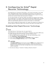
... setting Configure SATA as was previously not set to install the Intel Matrix Storage RAID driver during system POST. 2. Proceed to Advanced Drive Configuration. 3. Go to "Creating a Recovery Volume." 73 Enabling Intel Rapid Recover Technology NOTE Intel Rapid Recover Technology does not support RAID 5. Exit and save settings. 5 Configuring for Intel® Rapid Recover Technology Intel Rapid Recover technology utilizes RAID 1 (mirroring) functionality to copy data from a designated master drive to enable it. 4. You can be present on request. When using...
... setting Configure SATA as was previously not set to install the Intel Matrix Storage RAID driver during system POST. 2. Proceed to Advanced Drive Configuration. 3. Go to "Creating a Recovery Volume." 73 Enabling Intel Rapid Recover Technology NOTE Intel Rapid Recover Technology does not support RAID 5. Exit and save settings. 5 Configuring for Intel® Rapid Recover Technology Intel Rapid Recover technology utilizes RAID 1 (mirroring) functionality to copy data from a designated master drive to enable it. 4. You can be present on request. When using...


