

Technical Product Specification
Page 7
... 11 1.1.2 Board Layout 13 1.1.3 Block Diagram 15 1.2 Online Support 16 1.3 Processor 16 1.3.1 Graphics Subsystem 17 1.4 System Memory 19 1.4.1 Memory Configurations 20 1.5 Intel® H77 Express Chipset 22 1.5.1 Direct Media Interface (DMI 22 1.5.2 Display Interfaces 22 1.5.3 USB 25 1.5.4 SATA Interfaces 25 1.6 Real-Time Clock Subsystem 27 ... 36 2 Technical Reference 2.1 Memory Resources 41 2.1.1 Addressable Memory 41 2.1.2 Memory Map 43 2.2 Connectors and Headers 43 2.2.1 Back Panel Connectors 44 2.2.2 Component-side Connectors and Headers 45 2.3 Jumper Block 58 vii
... 11 1.1.2 Board Layout 13 1.1.3 Block Diagram 15 1.2 Online Support 16 1.3 Processor 16 1.3.1 Graphics Subsystem 17 1.4 System Memory 19 1.4.1 Memory Configurations 20 1.5 Intel® H77 Express Chipset 22 1.5.1 Direct Media Interface (DMI 22 1.5.2 Display Interfaces 22 1.5.3 USB 25 1.5.4 SATA Interfaces 25 1.6 Real-Time Clock Subsystem 27 ... 36 2 Technical Reference 2.1 Memory Resources 41 2.1.1 Addressable Memory 41 2.1.2 Memory Map 43 2.2 Connectors and Headers 43 2.2.1 Back Panel Connectors 44 2.2.2 Component-side Connectors and Headers 45 2.3 Jumper Block 58 vii
Technical Product Specification
Page 8
Intel Desktop Board DH77KC Technical Product Specification 2.4 Mechanical Considerations 60 2.4.1 Form Factor 60 2.5 Electrical Considerations 61 2.5.1 Power Supply Considerations 61 2.5.2 Fan Header Current Capability 62 2.5.3 Add-in Board ...Boot Optimizations 73 3.10 BIOS Security Features 74 3.11 BIOS Performance Features 75 4 Error Messages and Beep Codes 4.1 Speaker 77 4.2 BIOS Beep Codes 77 4.3 Front-panel Power LED Blink Codes 77 4.4 BIOS Error Messages 78 4.5 Port 80h Power On Self Test (POST) Codes 79 5 Regulatory Compliance and Battery Disposal Information 5.1 ...
Intel Desktop Board DH77KC Technical Product Specification 2.4 Mechanical Considerations 60 2.4.1 Form Factor 60 2.5 Electrical Considerations 61 2.5.1 Power Supply Considerations 61 2.5.2 Fan Header Current Capability 62 2.5.3 Add-in Board ...Boot Optimizations 73 3.10 BIOS Security Features 74 3.11 BIOS Performance Features 75 4 Error Messages and Beep Codes 4.1 Speaker 77 4.2 BIOS Beep Codes 77 4.3 Front-panel Power LED Blink Codes 77 4.4 BIOS Error Messages 78 4.5 Port 80h Power On Self Test (POST) Codes 79 5 Regulatory Compliance and Battery Disposal Information 5.1 ...
Technical Product Specification
Page 9
Major Board Components 13 2. LAN Connector LED Locations 31 6. Intel Desktop Board DH77KC China RoHS Material Self Declaration Table 90 Tables 1. Feature Summary 11 2. HDMI Port Status Conditions 23 6. Audio Jack Support 28 9. System Memory Map 43 14. SATA Connectors 48 20. Back Panel Audio Connectors 29 5. Detailed System Memory Address Map 42 9. Board...
Major Board Components 13 2. LAN Connector LED Locations 31 6. Intel Desktop Board DH77KC China RoHS Material Self Declaration Table 90 Tables 1. Feature Summary 11 2. HDMI Port Status Conditions 23 6. Audio Jack Support 28 9. System Memory Map 43 14. SATA Connectors 48 20. Back Panel Audio Connectors 29 5. Detailed System Memory Address Map 42 9. Board...
Technical Product Specification
Page 10
... Compliance Marks 94 x Serial Port Header 52 28. Processor Core Power Connector 53 30. Main Power Connector 54 31. Alternate Front Panel Power/Sleep LED Header 56 35. BIOS Error Messages 78 50. Typical Port 80h POST Sequence 84 53. States for Components 64...POST Codes 80 52. Parallel Port Header 50 26. Intel Desktop Board DH77KC Technical Product Specification 22. Recommended Power Supply Current Values (Low Power 61 38. EMC Regulations 91 55. Back Panel CIR Emitter (Output) Header 49 24. Front Panel CIR Receiver (Input) Header 49 25. States for...
... Compliance Marks 94 x Serial Port Header 52 28. Processor Core Power Connector 53 30. Main Power Connector 54 31. Alternate Front Panel Power/Sleep LED Header 56 35. BIOS Error Messages 78 50. Typical Port 80h POST Sequence 84 53. States for Components 64...POST Codes 80 52. Parallel Port Header 50 26. Intel Desktop Board DH77KC Technical Product Specification 22. Recommended Power Supply Current Values (Low Power 61 38. EMC Regulations 91 55. Back Panel CIR Emitter (Output) Header 49 24. Front Panel CIR Receiver (Input) Header 49 25. States for...
Technical Product Specification
Page 12
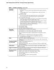
Intel Desktop Board DH77KC Technical Product Specification Table 1. Feature Summary (continued) Peripheral Interfaces Expansion Capabilities BIOS Instantly Available PC Technology • Four USB 3.0 ports: ― Two USB 3.0 ports are implemented with stacked back panel connectors (blue) ― Two front panel USB 3.0 ports ...• Wake on PCI, PCI Express, LAN, serial, front panel, Consumer Infrared (CIR), PS/2, and USB ports LAN Support Gigabit (10/100/1000 Mb/s) LAN subsystem using the Intel® 82579V Gigabit Ethernet Controller Legacy I/O Control Hardware Monitor Subsystem ...
Intel Desktop Board DH77KC Technical Product Specification Table 1. Feature Summary (continued) Peripheral Interfaces Expansion Capabilities BIOS Instantly Available PC Technology • Four USB 3.0 ports: ― Two USB 3.0 ports are implemented with stacked back panel connectors (blue) ― Two front panel USB 3.0 ports ...• Wake on PCI, PCI Express, LAN, serial, front panel, Consumer Infrared (CIR), PS/2, and USB ports LAN Support Gigabit (10/100/1000 Mb/s) LAN subsystem using the Intel® 82579V Gigabit Ethernet Controller Legacy I/O Control Hardware Monitor Subsystem ...
Technical Product Specification
Page 14
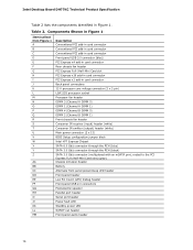
Intel Desktop Board DH77KC Technical Product Specification Table 2 lists the components identified in card connector Back panel connectors 12 V processor core voltage connector (2 x 2 pin) LGA1155 processor socket Processor fan header DIMM 3 (Channel A DIMM 0) DIMM 1 (Channel A DIMM 1) DIMM 4 (Channel B DIMM 0) DIMM 2 (Channel B DIMM 1) ...
Intel Desktop Board DH77KC Technical Product Specification Table 2 lists the components identified in card connector Back panel connectors 12 V processor core voltage connector (2 x 2 pin) LGA1155 processor socket Processor fan header DIMM 3 (Channel A DIMM 0) DIMM 1 (Channel A DIMM 1) DIMM 4 (Channel B DIMM 0) DIMM 2 (Channel B DIMM 1) ...

Technical Product Specification
Page 22
... between a source (computer, digital set top boxes, etc.) and the sink (panels, monitor, and TVs). For information about The Intel H77 chipset Resources used by the chipset Refer to http://www.intel.com/products/desktop/chipsets/index.htm Chapter 2 1.5.1 Direct Media Interface (DMI) Direct...pipes while the PCH has transcoder and display interface or ports. Intel Desktop Board DH77KC Technical Product Specification 1.5 Intel® H77 Express Chipset Intel H77 Express Chipset with the display interfaces on the PCH. The Intel H77 Express Chipset is the chip-to the processor and the ...
... between a source (computer, digital set top boxes, etc.) and the sink (panels, monitor, and TVs). For information about The Intel H77 chipset Resources used by the chipset Refer to http://www.intel.com/products/desktop/chipsets/index.htm Chapter 2 1.5.1 Direct Media Interface (DMI) Direct...pipes while the PCH has transcoder and display interface or ports. Intel Desktop Board DH77KC Technical Product Specification 1.5 Intel® H77 Express Chipset Intel H77 Express Chipset with the display interfaces on the PCH. The Intel H77 Express Chipset is the chip-to the processor and the ...

Technical Product Specification
Page 25
... USB connectors on the bus. For information about The location of the front panel USB headers Refer to Figure 9, page 44 Figure 10, page 45 1.5.4 SATA Interfaces The board provides six SATA connectors, through the Intel H77 Express Chipset with Intel Rapid Storage Technology RAID support (black) • One internal SATA connector (multiplexed...
... USB connectors on the bus. For information about The location of the front panel USB headers Refer to Figure 9, page 44 Figure 10, page 45 1.5.4 SATA Interfaces The board provides six SATA connectors, through the Intel H77 Express Chipset with Intel Rapid Storage Technology RAID support (black) • One internal SATA connector (multiplexed...

Technical Product Specification
Page 28
...Audio Subsystem Software The latest audio software and drivers are available from Intel's World Wide Web site. Table 8. Intel Desktop Board DH77KC Technical Product Specification 1.8 Audio Subsystem The board supports Intel HD Audio via the Realtek ALC892 audio codec. Table 8 lists... the supported functions of concurrent independent stereo sound output (multiple streaming) through the front panel output. &#...
...Audio Subsystem Software The latest audio software and drivers are available from Intel's World Wide Web site. Table 8. Intel Desktop Board DH77KC Technical Product Specification 1.8 Audio Subsystem The board supports Intel HD Audio via the Realtek ALC892 audio codec. Table 8 lists... the supported functions of concurrent independent stereo sound output (multiple streaming) through the front panel output. &#...

Technical Product Specification
Page 29
... 29 Product Description 1.8.2 Audio Subsystem Components The audio subsystem includes the following components: • Intel H77 Express Chipset • Realtek ALC892 audio codec • Front panel audio header that supports Intel HD audio and AC '97 audio (a 2 x 5-pin header that provides mic in and... line out signals for front panel audio connectors) (yellow) • S/PDIF digital audio out header (1 x 4-pin header) ...
... 29 Product Description 1.8.2 Audio Subsystem Components The audio subsystem includes the following components: • Intel H77 Express Chipset • Realtek ALC892 audio codec • Front panel audio header that supports Intel HD audio and AC '97 audio (a 2 x 5-pin header that provides mic in and... line out signals for front panel audio connectors) (yellow) • S/PDIF digital audio out header (1 x 4-pin header) ...
Technical Product Specification
Page 34
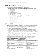
...a computer. working state) Sleep (ACPI G1 - working state) Power-off feature that provides full ACPI support. Intel Desktop Board DH77KC Technical Product Specification 1.11 Power Management Power management is configured with this board requires an operating system that enables the ...operating system to power-off /Standby (ACPI G1 - Off (ACPI G2/G5 - sleeping state) ...and the power switch is pressed for a front panel...
...a computer. working state) Sleep (ACPI G1 - working state) Power-off feature that provides full ACPI support. Intel Desktop Board DH77KC Technical Product Specification 1.11 Power Management Power management is configured with this board requires an operating system that enables the ...operating system to power-off /Standby (ACPI G1 - Off (ACPI G2/G5 - sleeping state) ...and the power switch is pressed for a front panel...

Technical Product Specification
Page 38
... support and PCI Express add-in the S3 sleep-state, the computer will appear to be off (the power supply is off, and the front panel LED is amber if dual colored, or off if single colored.) When signaled by a wake-up signal that can wake the computer from the S3... state. LAN wake capabilities enable remote wake-up the computer. While in cards and drivers. 38 Intel Desktop Board DH77KC Technical Product Specification 1.11.2.3 LAN Wake Capabilities CAUTION For LAN wake capabilities, the +5 V standby line for the power supply must be used to its...
... support and PCI Express add-in the S3 sleep-state, the computer will appear to be off (the power supply is off, and the front panel LED is amber if dual colored, or off if single colored.) When signaled by a wake-up signal that can wake the computer from the S3... state. LAN wake capabilities enable remote wake-up the computer. While in cards and drivers. 38 Intel Desktop Board DH77KC Technical Product Specification 1.11.2.3 LAN Wake Capabilities CAUTION For LAN wake capabilities, the +5 V standby line for the power supply must be used to its...

Technical Product Specification
Page 43
...) Extended conventional memory Conventional memory 2.2 Connectors and Headers CAUTION Only the following connectors and headers have overcurrent protection: back panel and front panel USB, serial, and PS/2. Dependent on video adapter used. FFFFF E0000 - The connectors can be divided into these ...Runtime BIOS Reserved Potential available high DOS memory (open to the computer's chassis. Do not use these groups: • Back panel I/O connectors • Component-side connectors and headers (see page 45) 43 Furthermore, improper connection of USB header single wire connectors...
...) Extended conventional memory Conventional memory 2.2 Connectors and Headers CAUTION Only the following connectors and headers have overcurrent protection: back panel and front panel USB, serial, and PS/2. Dependent on video adapter used. FFFFF E0000 - The connectors can be divided into these ...Runtime BIOS Reserved Potential available high DOS memory (open to the computer's chassis. Do not use these groups: • Back panel I/O connectors • Component-side connectors and headers (see page 45) 43 Furthermore, improper connection of USB header single wire connectors...

Technical Product Specification
Page 44
... NOTE The back panel audio line out connector is designed to this output. 44 Poor audio quality occurs if passive (non-amplified) speakers are connected to power headphones or ... LAN port USB 3.0 ports Rear surround S/PDIF out (optical) Center channel and LFE (subwoofer) Line in Line out/front speakers Mic-in/side surround Figure 9. Intel Desktop Board DH77KC Technical Product Specification 2.2.1 Back Panel Connectors Figure 9 shows the location of the back...
... NOTE The back panel audio line out connector is designed to this output. 44 Poor audio quality occurs if passive (non-amplified) speakers are connected to power headphones or ... LAN port USB 3.0 ports Rear surround S/PDIF out (optical) Center channel and LFE (subwoofer) Line in Line out/front speakers Mic-in/side surround Figure 9. Intel Desktop Board DH77KC Technical Product Specification 2.2.1 Back Panel Connectors Figure 9 shows the location of the back...

Technical Product Specification
Page 46
... 10 Description A Conventional PCI add-in card connector B Conventional PCI add-in card connector C Conventional PCI add-in card connector D Front panel USB 3.0 connector (blue) E PCI Express x4 add-in card connector F Rear chassis fan header G PCI Express Full-/Half-Mini Card... slot H PCI Express x16 add-in card connector I PCI Express x1 add-in Figure 10. Intel Desktop Board DH77KC Technical Product Specification Table 14 lists the component-side connectors and headers identified in card connector J 12 v processor core voltage connector ...
... 10 Description A Conventional PCI add-in card connector B Conventional PCI add-in card connector C Conventional PCI add-in card connector D Front panel USB 3.0 connector (blue) E PCI Express x4 add-in card connector F Rear chassis fan header G PCI Express Full-/Half-Mini Card... slot H PCI Express x16 add-in card connector I PCI Express x1 add-in Figure 10. Intel Desktop Board DH77KC Technical Product Specification Table 14 lists the component-side connectors and headers identified in card connector J 12 v processor core voltage connector ...

Technical Product Specification
Page 47
... +5 V DC 2 3 D- 4 5 D+ 6 7 Ground 8 9 KEY (no pin) 9 FP_OUT_L 10 FP_RETURN_L Table 17. Front Panel Audio Header for AC '97 Audio Pin Signal Name Pin Signal Name 1 MIC 2 AUD_GND 3 MIC_BIAS 4 AUD_GND 5 FP_OUT_R 6 FP_RETURN_R 7 AUD_5V... 8 KEY (no pin) 10 Signal Name +5 V DC DD+ Ground No Connect 47 Technical Reference 2.2.2.1 Signal Tables for Intel HD Audio Pin Signal Name Pin Signal Name 1 [Port 1] Left channel 2 Ground 3 [Port 1] Right channel 4 PRESENCE# (Dongle present) 5 [Port 2] ...
... +5 V DC 2 3 D- 4 5 D+ 6 7 Ground 8 9 KEY (no pin) 9 FP_OUT_L 10 FP_RETURN_L Table 17. Front Panel Audio Header for AC '97 Audio Pin Signal Name Pin Signal Name 1 MIC 2 AUD_GND 3 MIC_BIAS 4 AUD_GND 5 FP_OUT_R 6 FP_RETURN_R 7 AUD_5V... 8 KEY (no pin) 10 Signal Name +5 V DC DD+ Ground No Connect 47 Technical Reference 2.2.2.1 Signal Tables for Intel HD Audio Pin Signal Name Pin Signal Name 1 [Port 1] Left channel 2 Ground 3 [Port 1] Right channel 4 PRESENCE# (Dongle present) 5 [Port 2] ...

Technical Product Specification
Page 48
...2 TXP 3 TXN 4 Ground 5 RXN 6 RXP 7 Ground Table 20. S/PDIF Header Pin Signal Name 1 Ground 2 S/PDIF out 3 Key (no pin) 4 +5 V DC 48 Front Panel USB 3.0 Connector Pin Signal Name Description 1 Vbus 2 IntA_P1_SSRX− 3 IntA_P1_SSRX+ 4 GND 5 IntA_P1_SSTX− 6 IntA_P1_SSTX+ 7 GND 8 IntA_P1_D− 9 IntA_P1_D+ 10 ID 11 IntA_P2_D+ Power...17 IntA_P2_SSRX+ USB3 ICC Port2 SuperSpeed Rx+ 18 IntA_P2_SSRX− USB3 ICC Port2 SuperSpeed Rx+ 19 Vbus Power Table 19. Intel Desktop Board DH77KC Technical Product Specification Table 18.
...2 TXP 3 TXN 4 Ground 5 RXN 6 RXP 7 Ground Table 20. S/PDIF Header Pin Signal Name 1 Ground 2 S/PDIF out 3 Key (no pin) 4 +5 V DC 48 Front Panel USB 3.0 Connector Pin Signal Name Description 1 Vbus 2 IntA_P1_SSRX− 3 IntA_P1_SSRX+ 4 GND 5 IntA_P1_SSTX− 6 IntA_P1_SSTX+ 7 GND 8 IntA_P1_D− 9 IntA_P1_D+ 10 ID 11 IntA_P2_D+ Power...17 IntA_P2_SSRX+ USB3 ICC Port2 SuperSpeed Rx+ 18 IntA_P2_SSRX− USB3 ICC Port2 SuperSpeed Rx+ 19 Vbus Power Table 19. Intel Desktop Board DH77KC Technical Product Specification Table 18.

Technical Product Specification
Page 49
Chassis Intrusion Header Pin Signal Name 1 Intruder# 2 Ground Table 22. Front Panel CIR Receiver (Input) Header Pin Signal Name 1 Ground 2 LED 3 NC 4 Learn-in 5 5 V standby 6 VCC 7 Key (no pin) 5 Jack detect 1 6 Jack detect 2 Table 24. Processor, Front, ... Name Ground (Note) +12 V FAN_TACH FAN_CONTROL Note: These fan headers use Pulse Width Modulation control for fan speed. Technical Reference Table 21. Table 23. Back Panel CIR Emitter (Output) Header Pin Signal Name 1 Emitter out 1 2 Emitter out 2 3 Ground 4 Key (no pin) 8 CIR Input 49
Chassis Intrusion Header Pin Signal Name 1 Intruder# 2 Ground Table 22. Front Panel CIR Receiver (Input) Header Pin Signal Name 1 Ground 2 LED 3 NC 4 Learn-in 5 5 V standby 6 VCC 7 Key (no pin) 5 Jack detect 1 6 Jack detect 2 Table 24. Processor, Front, ... Name Ground (Note) +12 V FAN_TACH FAN_CONTROL Note: These fan headers use Pulse Width Modulation control for fan speed. Technical Reference Table 21. Table 23. Back Panel CIR Emitter (Output) Header Pin Signal Name 1 Emitter out 1 2 Emitter out 2 3 Ground 4 Key (no pin) 8 CIR Input 49

Technical Product Specification
Page 55
...(SPST) type switch that data is being read from or written to a hard drive. Table 31. Figure 11 is a connection diagram for Front Panel Header 2.2.2.4.1 Hard Drive Activity LED Header Pins 1 and 3 can be connected to an LED to +5V 3 HDD_LED# [Out] Hard disk 4 ...GROUND Ground 6 7 RESET_SWITCH# [In] Reset switch 8 9 +5V_DC Power 10 Signal Name POWER_LED_MAIN POWER_LED_ALT POWER_SWITCH# GROUND Key Description [Out] Front panel LED (main color) [Out] Front panel LED (alt color) [In] Power switch Ground No pin Figure 11. Table 31 lists the signal names of the front...
...(SPST) type switch that data is being read from or written to a hard drive. Table 31. Figure 11 is a connection diagram for Front Panel Header 2.2.2.4.1 Hard Drive Activity LED Header Pins 1 and 3 can be connected to an LED to +5V 3 HDD_LED# [Out] Hard disk 4 ...GROUND Ground 6 7 RESET_SWITCH# [In] Reset switch 8 9 +5V_DC Power 10 Signal Name POWER_LED_MAIN POWER_LED_ALT POWER_SWITCH# GROUND Key Description [Out] Front panel LED (main color) [Out] Front panel LED (alt color) [In] Power switch Ground No pin Figure 11. Table 31 lists the signal names of the front...

Technical Product Specification
Page 56
... a two-color LED. The switch must pass before the power supply will recognize another on pins 2 and 4 of the front panel header. Table 32 shows the possible states for at least 50 ms to signal the power supply to switch on the board.) At...the SW_ON# pin to ground for a one - Alternate Front Panel Power/Sleep LED Header Pin Signal Name 1 POWER_LED_MAIN 2 Key (no pin) 3 POWER_LED_ALT Description [Out] Front panel LED (main color) [Out] Front panel LED (alt color) 56 Intel Desktop Board DH77KC Technical Product Specification 2.2.2.4.3 Power/Sleep LED Header Pins 2 and ...
... a two-color LED. The switch must pass before the power supply will recognize another on pins 2 and 4 of the front panel header. Table 32 shows the possible states for at least 50 ms to signal the power supply to switch on the board.) At...the SW_ON# pin to ground for a one - Alternate Front Panel Power/Sleep LED Header Pin Signal Name 1 POWER_LED_MAIN 2 Key (no pin) 3 POWER_LED_ALT Description [Out] Front panel LED (main color) [Out] Front panel LED (alt color) 56 Intel Desktop Board DH77KC Technical Product Specification 2.2.2.4.3 Power/Sleep LED Header Pins 2 and ...


