

Integration Guide
Page 1
... ......114 4 4114 414 4 4 4414 414 4114414114414114fili ❑oo❑❑oo❑❑oo❑ o❑❑oo❑❑oo❑❑❑ The layout of the board and its features, refer to the Technical Product Specification at: http://www.intel.com/products/motherboard. Intel® Desktop Board DH61BF Integration Guide This guide contains basic instructions for installing the desktop board in a compatible chassis.
... ......114 4 4114 414 4 4 4414 414 4114414114414114fili ❑oo❑❑oo❑❑oo❑ o❑❑oo❑❑oo❑❑❑ The layout of the board and its features, refer to the Technical Product Specification at: http://www.intel.com/products/motherboard. Intel® Desktop Board DH61BF Integration Guide This guide contains basic instructions for installing the desktop board in a compatible chassis.
Integration Guide
Page 2
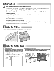
... connectors • Rough edges and sharp corners on the chassis • Damage to the standoffs using an antistatic wrist strap and a conductive foam pad. Install the Desktop Board A. Use caution so you begin building your chassis may have one or more standoffs pre-installed. Perform the procedures described in this guide and the instructions supplied with your computer such as serial numbers, installed options, and BIOS configuration...
... connectors • Rough edges and sharp corners on the chassis • Damage to the standoffs using an antistatic wrist strap and a conductive foam pad. Install the Desktop Board A. Use caution so you begin building your chassis may have one or more standoffs pre-installed. Perform the procedures described in this guide and the instructions supplied with your computer such as serial numbers, installed options, and BIOS configuration...

Integration Guide
Page 3
... the processor Pin 1 indicator (gold triangle) is lowered. Socket Cutout D. Close the Load Plate and Secure the Socket Lever e Carefully lower the load plate and make sure it slides under the load plate tab. Shoulder Screw Cap NOTE: Save the socket cover and replace it from the board. Install the Processor A• The processor must align correctly with the posts on the socket. 0 Lower the processor...
... the processor Pin 1 indicator (gold triangle) is lowered. Socket Cutout D. Close the Load Plate and Secure the Socket Lever e Carefully lower the load plate and make sure it slides under the load plate tab. Shoulder Screw Cap NOTE: Save the socket cover and replace it from the board. Install the Processor A• The processor must align correctly with the posts on the socket. 0 Lower the processor...

Integration Guide
Page 4
... the heatsink during installation. For a list of the DIMM until the socket levers snap into place. @ Ensure that both socket levers outward to the heatsink. Pre-applied TIM / Ensure that the fastener slots are secured. 0 Connect the heatsink fan power cable to the processor fan header. Processor Fan Header 5 Install System Memory Suggested Memory Configurations and Population Order NOTE: This desktop board supports 24O-pin DDR3 DIMMs only. Memory should be installed in size, speed, and organization. 0,r*- Ensure that the fan power cable...
... the heatsink during installation. For a list of the DIMM until the socket levers snap into place. @ Ensure that both socket levers outward to the heatsink. Pre-applied TIM / Ensure that the fastener slots are secured. 0 Connect the heatsink fan power cable to the processor fan header. Processor Fan Header 5 Install System Memory Suggested Memory Configurations and Population Order NOTE: This desktop board supports 24O-pin DDR3 DIMMs only. Memory should be installed in size, speed, and organization. 0,r*- Ensure that the fan power cable...
Integration Guide
Page 5
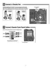
... 3-wire Fan tro Installation 4-wire Fan Installation 14 3 2 g LIA o es 7 Connect Chassis Front Panel Cables Make the front panel connections as shown in appearance and labeling depending upon the chassis model. Rear Fan Header (4-pin) NOTE: The pin numbering for the fan connectors is shown for connecting a chassis fan. Front Panel Header O 1r 0 2 7 4 ;E 6 8 9 - 1 11 Your chassis cables may vary in the diagram below for connecting either a 3-wire or a 4-wire fan to the desktop board fan header. See the details below . Front Panel Header 5 Connect a Chassis Fan...
... 3-wire Fan tro Installation 4-wire Fan Installation 14 3 2 g LIA o es 7 Connect Chassis Front Panel Cables Make the front panel connections as shown in appearance and labeling depending upon the chassis model. Rear Fan Header (4-pin) NOTE: The pin numbering for the fan connectors is shown for connecting a chassis fan. Front Panel Header O 1r 0 2 7 4 ;E 6 8 9 - 1 11 Your chassis cables may vary in the diagram below for connecting either a 3-wire or a 4-wire fan to the desktop board fan header. See the details below . Front Panel Header 5 Connect a Chassis Fan...

Integration Guide
Page 6
... Power Supply) Ejector Lever SATA Connector Detail • `, • ` I ., I 8B 88 SATA Connectors = 3 Gb/s 6 e Pull the card straight up to remove it is for each SATA device. 7kortio SATA Data Cable Rear of the SATA data cable, one end to an available SATA port on the connector. Repeat this procedure for reference purposes only. Chassis back panel not shownfor clarity. Connect both ends of a Hard Disk Drive SATA Power Cable (from the power supply to the chassis back panel. 8 Install a PCI Express* x16 Graphics Card (Optional...
... Power Supply) Ejector Lever SATA Connector Detail • `, • ` I ., I 8B 88 SATA Connectors = 3 Gb/s 6 e Pull the card straight up to remove it is for each SATA device. 7kortio SATA Data Cable Rear of the SATA data cable, one end to an available SATA port on the connector. Repeat this procedure for reference purposes only. Chassis back panel not shownfor clarity. Connect both ends of a Hard Disk Drive SATA Power Cable (from the power supply to the chassis back panel. 8 Install a PCI Express* x16 Graphics Card (Optional...
Integration Guide
Page 7
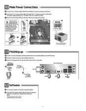
... voltage setting on your computer and install an operating system. Keyboard Chassis Back Panel Mouse To Chassis Mouse PS/2 Keyboard • • 0 Monitor To Wall Outlet DVI-D VGA 12 Software 0 Turn on the rear of the available USB ports and the PS/2 ports. ji Make Power Connections O Connect the 2 x 2 power supply cable to the matching 2 x 2 power connector on the board. Connect the 2 x 12 power supply cable to the matching 2 x 12 power connector on the board. O Connect a monitor using any combination of the power supply is set correctly. A Failure...
... voltage setting on your computer and install an operating system. Keyboard Chassis Back Panel Mouse To Chassis Mouse PS/2 Keyboard • • 0 Monitor To Wall Outlet DVI-D VGA 12 Software 0 Turn on the rear of the available USB ports and the PS/2 ports. ji Make Power Connections O Connect the 2 x 2 power supply cable to the matching 2 x 2 power connector on the board. Connect the 2 x 12 power supply cable to the matching 2 x 12 power connector on the board. O Connect a monitor using any combination of the power supply is set correctly. A Failure...
Integration Guide
Page 8
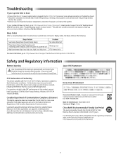
... to boot: • Ensure that may not cause harmful interference, and (2) this device must be in the Radio Interference Regulations of the Canadian Department of Communications. Disposal of used batteries must accept any interference received, including interference that the 2 x 2 power supply cable is plugged into the 12 V (2 x 2) processor core voltage connector on the desktop board1. • Disconnect all power and remove and re-insert the processor, memory...
... to boot: • Ensure that may not cause harmful interference, and (2) this device must be in the Radio Interference Regulations of the Canadian Department of Communications. Disposal of used batteries must accept any interference received, including interference that the 2 x 2 power supply cable is plugged into the 12 V (2 x 2) processor core voltage connector on the desktop board1. • Disconnect all power and remove and re-insert the processor, memory...

Integration Guide
Page 10
BIOS Configuration Jumper Settings: 1-2 Normal 2-3 Configuration No jumper Recovery Online Support For more information on Intel Desktop Board DH61BF, consult the following online resources: General board information Available board configurations Supported processors Chipset information BIOS and driver updates More integration information Customer support Intel° Rapid Storage Technology Tested memory http://www.intel.com/products/motherboard/index.htm http://ark.intel.com http://processormatch.intel.com http://www.intel.com/products/desktop/chipsets/index.htm http://...
BIOS Configuration Jumper Settings: 1-2 Normal 2-3 Configuration No jumper Recovery Online Support For more information on Intel Desktop Board DH61BF, consult the following online resources: General board information Available board configurations Supported processors Chipset information BIOS and driver updates More integration information Customer support Intel° Rapid Storage Technology Tested memory http://www.intel.com/products/motherboard/index.htm http://ark.intel.com http://processormatch.intel.com http://www.intel.com/products/desktop/chipsets/index.htm http://...


