
Technical Product Specification
Page 8
Intel Desktop Board DH61BE Technical Product Specification 1.15 Platform Management and Security 30 1.15.1 Hardware Management Subsystem 30 1.15.2 Hardware Monitoring 30 1.16 Power Management 31 1.16.1 ACPI 31 1.16.2 Hardware Support 34 2 Technical Reference 2.1 Memory Resources 39 2.1.1 Addressable Memory 39 2.1.2 Memory Map 41 2.2 Connectors and Headers 41 2.2.1 Back Panel... Connectors 42 2.2.2 Component-side Connectors and Headers 43 2.3 BIOS Configuration Jumper Block 52 2.4 Intel® Management Engine BIOS Extension (Intel® MEBX) Reset ...
Intel Desktop Board DH61BE Technical Product Specification 1.15 Platform Management and Security 30 1.15.1 Hardware Management Subsystem 30 1.15.2 Hardware Monitoring 30 1.16 Power Management 31 1.16.1 ACPI 31 1.16.2 Hardware Support 34 2 Technical Reference 2.1 Memory Resources 39 2.1.1 Addressable Memory 39 2.1.2 Memory Map 41 2.2 Connectors and Headers 41 2.2.1 Back Panel... Connectors 42 2.2.2 Component-side Connectors and Headers 43 2.3 BIOS Configuration Jumper Block 52 2.4 Intel® Management Engine BIOS Extension (Intel® MEBX) Reset ...
Technical Product Specification
Page 9
... of Pressing the Power Switch 31 7. LAN Connector LED States 27 6. System Memory Map 41 10. Back Panel Audio Connector Options 25 5. Intel MEBX Reset Header 54 15. Feature Summary 11 2. Internal Mono Speaker Header 45 15. Block Diagram 15 3....27 6. Components Shown in Figure 10 44 11. Component-side Connectors and Headers Shown in Figure 1 14 3. Connection Diagram for Front Panel USB Headers 51 13. Memory Channel and DIMM Configuration 19 4. Location of Conformity Statement 76 5.1.3 Product Ecology Statements 77 5.1.4 EMC Regulations...
... of Pressing the Power Switch 31 7. LAN Connector LED States 27 6. System Memory Map 41 10. Back Panel Audio Connector Options 25 5. Intel MEBX Reset Header 54 15. Feature Summary 11 2. Internal Mono Speaker Header 45 15. Block Diagram 15 3....27 6. Components Shown in Figure 10 44 11. Component-side Connectors and Headers Shown in Figure 1 14 3. Connection Diagram for Front Panel USB Headers 51 13. Memory Channel and DIMM Configuration 19 4. Location of Conformity Statement 76 5.1.3 Product Ecology Statements 77 5.1.4 EMC Regulations...
Technical Product Specification
Page 10
... Current Capability 57 31. Boot Device Menu Options 66 37. Typical Port 80h POST Sequence 74 43. Intel Desktop Board DH61BE Technical Product Specification 16. Recommended Power Supply Current Values 56 30. Safety Standards 75 44. EMC Regulations 79... 45. Chassis Intrusion Header 47 20. BIOS Error Messages 68 40. LPC Debug Header 51 27. Environmental Specifications 60 33. Front-panel Power LED Blink Codes 68 39. Intel...
... Current Capability 57 31. Boot Device Menu Options 66 37. Typical Port 80h POST Sequence 74 43. Intel Desktop Board DH61BE Technical Product Specification 16. Recommended Power Supply Current Values 56 30. Safety Standards 75 44. EMC Regulations 79... 45. Chassis Intrusion Header 47 20. BIOS Error Messages 68 40. LPC Debug Header 51 27. Environmental Specifications 60 33. Front-panel Power LED Blink Codes 68 39. Intel...

Technical Product Specification
Page 11
....84 millimeters by 198.12 millimeters]) • Intel® Core™ i7, Intel® Core™ i5, Intel® Core™ i3, and Intel® Pentium® processors in an LGA1155 socket... graphics processing (processors with Intel® Graphics Technology) ― External graphics interface controller ― Integrated memory controller Intel® H61 Express Chipset consisting of the Intel® H61 Platform Controller Hub...-ECC memory • Integrated graphics support for processors with Intel® Graphics Technology: ― VGA ― DVI-D • Discrete graphics support for PCI...
....84 millimeters by 198.12 millimeters]) • Intel® Core™ i7, Intel® Core™ i5, Intel® Core™ i3, and Intel® Pentium® processors in an LGA1155 socket... graphics processing (processors with Intel® Graphics Technology) ― External graphics interface controller ― Integrated memory controller Intel® H61 Express Chipset consisting of the Intel® H61 Platform Controller Hub...-ECC memory • Integrated graphics support for processors with Intel® Graphics Technology: ― VGA ― DVI-D • Discrete graphics support for PCI...
Technical Product Specification
Page 12
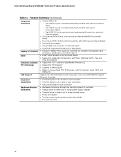
...Intel Desktop Board DH61BE Technical Product Specification Table 1. Feature Summary (continued) Peripheral Interfaces Legacy I/O Control BIOS • Twelve USB ports: ― Two USB 3.0 ports are implemented with stacked back panel connectors (blue) ― Two USB 2.0 ports are implemented with stacked back panel connectors (black) ― Eight USB 2.0 front panel... • Wake on Conventional PCI, PCI Express, LAN, front panel, serial, PS/2, and USB ports Gigabit (10/100/1000 Mbits/s) LAN subsystem using the Intel® 82579V Gigabit Ethernet Controller • One PCI Express 2.0 ...
...Intel Desktop Board DH61BE Technical Product Specification Table 1. Feature Summary (continued) Peripheral Interfaces Legacy I/O Control BIOS • Twelve USB ports: ― Two USB 3.0 ports are implemented with stacked back panel connectors (blue) ― Two USB 2.0 ports are implemented with stacked back panel connectors (black) ― Eight USB 2.0 front panel... • Wake on Conventional PCI, PCI Express, LAN, front panel, serial, PS/2, and USB ports Gigabit (10/100/1000 Mbits/s) LAN subsystem using the Intel® 82579V Gigabit Ethernet Controller • One PCI Express 2.0 ...
Technical Product Specification
Page 14
... S/PDIF header PCI Express x1 add-in card connector Battery PCI Express x16 add-in card connector Back panel connectors Front panel USB 2.0 header Standby power LED 12 V internal power connector (ATX12V) Rear chassis fan header Piezoelectric speaker... jumper block Front panel header Alternate front panel power LED header Intel® Management Engine BIOS Extension (Intel® MEBX) Reset header Intel H61 Express Chipset Serial port header Front panel USB 2.0 headers (3) Internal mono speaker header Front panel audio header 14 Intel Desktop Board DH61BE Technical Product Specification Table...
... S/PDIF header PCI Express x1 add-in card connector Battery PCI Express x16 add-in card connector Back panel connectors Front panel USB 2.0 header Standby power LED 12 V internal power connector (ATX12V) Rear chassis fan header Piezoelectric speaker... jumper block Front panel header Alternate front panel power LED header Intel® Management Engine BIOS Extension (Intel® MEBX) Reset header Intel H61 Express Chipset Serial port header Front panel USB 2.0 headers (3) Internal mono speaker header Front panel audio header 14 Intel Desktop Board DH61BE Technical Product Specification Table...
Technical Product Specification
Page 21
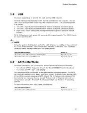
... NOTE Computer systems that meets the requirements for full-speed devices. For information about The location of the USB connectors on the back panel The location of the SATA connectors Refer to Figure 9, page 42 Figure 10, page 43 1.9 SATA Interfaces The board provides six SATA... connector: • Two internal SATA 6 Gb/s ports through four dual-port internal headers All 12 USB ports are super-speed capable. The Intel H61 Express Chipset provides the USB controller for configurations using the Windows* XP, Windows Vista*, and Windows 7* operating systems. For more information, ...
... NOTE Computer systems that meets the requirements for full-speed devices. For information about The location of the USB connectors on the back panel The location of the SATA connectors Refer to Figure 9, page 42 Figure 10, page 43 1.9 SATA Interfaces The board provides six SATA... connector: • Two internal SATA 6 Gb/s ports through four dual-port internal headers All 12 USB ports are super-speed capable. The Intel H61 Express Chipset provides the USB controller for configurations using the Windows* XP, Windows Vista*, and Windows 7* operating systems. For more information, ...
Technical Product Specification
Page 22
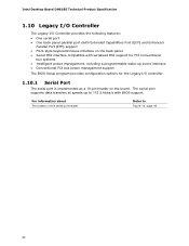
... IRQ support for the Legacy I /O Controller provides the following features: • One serial port • One back panel parallel port (with Extended Capabilities Port (ECP) and Enhanced Parallel Port (EPP) support • PS/2-style keyboard/mouse interface on the ... configuration options for PCI Conventional bus systems • Intelligent power management, including a programmable wake-up to Figure 10, page 43 22 Intel Desktop Board DH61BE Technical Product Specification 1.10 Legacy I/O Controller The Legacy I /O controller. 1.10.1 Serial Port The serial port is implemented as a...
... IRQ support for the Legacy I /O Controller provides the following features: • One serial port • One back panel parallel port (with Extended Capabilities Port (ECP) and Enhanced Parallel Port (EPP) support • PS/2-style keyboard/mouse interface on the ... configuration options for PCI Conventional bus systems • Intelligent power management, including a programmable wake-up to Figure 10, page 43 22 Intel Desktop Board DH61BE Technical Product Specification 1.10 Legacy I/O Controller The Legacy I /O controller. 1.10.1 Serial Port The serial port is implemented as a...

Technical Product Specification
Page 23
... Center/ Surround Sub Default Default Side Surround Default 23 Product Description 1.11 Audio Subsystem The board supports Intel High Definition Audio through back panel jacks • Headphone and Mic in functions for the back panel audio jacks that enables the audio codec to recognize the device that is connected to an audio port...
... Center/ Surround Sub Default Default Side Surround Default 23 Product Description 1.11 Audio Subsystem The board supports Intel High Definition Audio through back panel jacks • Headphone and Mic in functions for the back panel audio jacks that enables the audio codec to recognize the device that is connected to an audio port...
Technical Product Specification
Page 24
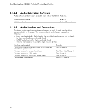
... the component side of the board. The component-side audio headers include the following: • Front panel audio (a 2 x 5-pin header that provides headphone and mic in signals for front panel audio connectors) (yellow) • S/PDIF audio header (1 x 4-pin header) (yellow) • Internal mono speaker header (1 x 2-pin header) (yellow) For ...Figure 10, page 43 Table 15 and Table 16, page 46 Table 13, page 45 Table 14, page 45 Section 2.2.1, page 42 24 Intel Desktop Board DH61BE Technical Product Specification 1.11.1 Audio Subsystem Software Audio software and drivers are available from...
... the component side of the board. The component-side audio headers include the following: • Front panel audio (a 2 x 5-pin header that provides headphone and mic in signals for front panel audio connectors) (yellow) • S/PDIF audio header (1 x 4-pin header) (yellow) • Internal mono speaker header (1 x 2-pin header) (yellow) For ...Figure 10, page 43 Table 15 and Table 16, page 46 Table 13, page 45 Table 14, page 45 Section 2.2.1, page 42 24 Intel Desktop Board DH61BE Technical Product Specification 1.11.1 Audio Subsystem Software Audio software and drivers are available from...

Technical Product Specification
Page 25
...for basic system sound capability. Product Description 1.11.2.1 Analog Audio Connectors The available configurable back panel audio connectors are configurable through back panel speakers and a front panel headset, respectively). 1.11.2.2 S/PDIF Header The S/PDIF header allows connections to coaxial or...optical dongles for digital audio output. 1.11.2.3 Internal Mono Speaker Header The internal mono speaker header allows connection to Section 2.2.1, page 42 The front panel headphone output is capable of driving a speaker load of 8 Ohms at 1 W (rms) or 4 Ohms at 1.5 W (rms). 25 ...
...for basic system sound capability. Product Description 1.11.2.1 Analog Audio Connectors The available configurable back panel audio connectors are configurable through back panel speakers and a front panel headset, respectively). 1.11.2.2 S/PDIF Header The S/PDIF header allows connections to coaxial or...optical dongles for digital audio output. 1.11.2.3 Internal Mono Speaker Header The internal mono speaker header allows connection to Section 2.2.1, page 42 The front panel headphone output is capable of driving a speaker load of 8 Ohms at 1 W (rms) or 4 Ohms at 1.5 W (rms). 25 ...
Technical Product Specification
Page 31
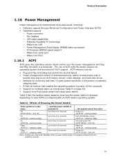
... and Plug and Play functions of Pressing the Power Switch If the system is in this state... ...and the power switch is pressed for a front panel power and sleep mode switch Table 6 lists the system states based on how long the power switch is pressed, depending on (ACPI G0 - Table 6. working...
... and Plug and Play functions of Pressing the Power Switch If the system is in this state... ...and the power switch is pressed for a front panel power and sleep mode switch Table 6 lists the system states based on how long the power switch is pressed, depending on (ACPI G0 - Table 6. working...
Technical Product Specification
Page 36
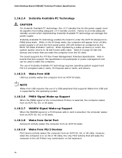
...16.2.5 Wake from USB USB bus activity wakes the computer from USB requires the use of providing adequate +5 V standby current. Intel Desktop Board DH61BE Technical Product Specification 1.16.2.4 Instantly Available PC Technology CAUTION For Instantly Available PC technology, the +5 V standby line for the power... supply must be off (the power supply is off and the front panel power LED will behave as configured by the ...
...16.2.5 Wake from USB USB bus activity wakes the computer from USB requires the use of providing adequate +5 V standby current. Intel Desktop Board DH61BE Technical Product Specification 1.16.2.4 Instantly Available PC Technology CAUTION For Instantly Available PC technology, the +5 V standby line for the power... supply must be off (the power supply is off and the front panel power LED will behave as configured by the ...
Technical Product Specification
Page 41
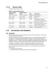
... presented by memory manager software) Extended conventional memory Conventional memory 2.2 Connectors and Headers CAUTION Only the following connectors and headers have overcurrent protection: back panel and front panel USB, and PS/2. System Memory Map Address Range (decimal) Address Range (hex) 1024 K - 16777216 K 100000 - 400000000 960 K - ... DFFFF 640 K - 800 K 639 K - 640 K 512 K - 639 K 0 K - 512 K A0000 - Table 9. FFFFF 896 K - 960 K E0000 - Do not use these groups: • Back panel I/O connectors • Component-side I/O connectors and headers (see page 43) 41
... presented by memory manager software) Extended conventional memory Conventional memory 2.2 Connectors and Headers CAUTION Only the following connectors and headers have overcurrent protection: back panel and front panel USB, and PS/2. System Memory Map Address Range (decimal) Address Range (hex) 1024 K - 16777216 K 100000 - 400000000 960 K - ... DFFFF 640 K - 800 K 639 K - 640 K 512 K - 639 K 0 K - 512 K A0000 - Table 9. FFFFF 896 K - 960 K E0000 - Do not use these groups: • Back panel I/O connectors • Component-side I/O connectors and headers (see page 43) 41

Technical Product Specification
Page 42
... if passive (non-amplified) speakers are connected to power headphones or amplified speakers only. Intel Desktop Board DH61BE Technical Product Specification 2.2.1 Back Panel Connectors Figure 9 shows the location of the back panel connectors for the board. Back Panel Connectors NOTE The back panel audio line out connector is designed to this output. 42 Item A B C D E F G H I J K L M Description PS...
... if passive (non-amplified) speakers are connected to power headphones or amplified speakers only. Intel Desktop Board DH61BE Technical Product Specification 2.2.1 Back Panel Connectors Figure 9 shows the location of the back panel connectors for the board. Back Panel Connectors NOTE The back panel audio line out connector is designed to this output. 42 Item A B C D E F G H I J K L M Description PS...

Technical Product Specification
Page 44
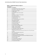
...D S/PDIF header E PCI Express x1 add-in card connector F PCI Express x16 bus add-in card connector G Front panel USB 2.0 header H 12 V internal power connector (ATX12V) I Rear chassis fan header J Processor fan header K Front chassis... (black)) P Front panel header Q Alternate front panel power LED header R Intel MEBX Reset header S Serial port header T Front panel USB 2.0 header U Front panel USB 2.0 header V Front panel USB 2.0 header W Internal mono speaker header X Front panel audio header 44 Intel Desktop Board DH61BE Technical Product Specification Table...
...D S/PDIF header E PCI Express x1 add-in card connector F PCI Express x16 bus add-in card connector G Front panel USB 2.0 header H 12 V internal power connector (ATX12V) I Rear chassis fan header J Processor fan header K Front chassis... (black)) P Front panel header Q Alternate front panel power LED header R Intel MEBX Reset header S Serial port header T Front panel USB 2.0 header U Front panel USB 2.0 header V Front panel USB 2.0 header W Internal mono speaker header X Front panel audio header 44 Intel Desktop Board DH61BE Technical Product Specification Table...

Technical Product Specification
Page 46
specifically, pins 4, 6, 7, and 10 are supported; Table 17. SATA Connectors Pin Signal Name 1 Ground 2 TXP 3 TXN 4 Ground 5 RXN 6 RXP 7 Ground 46 Intel Desktop Board DH61BE Technical Product Specification Table 15. Front Panel Audio Header for AC '97 Audio Pin Signal Name Pin Signal Name 1 MIC 2 AUD_GND 3 MIC_BIAS 4 AUD_GND 5 FP_OUT_R 6 FP_RETURN_R 7 AUD_5V 8 KEY (no pin...
specifically, pins 4, 6, 7, and 10 are supported; Table 17. SATA Connectors Pin Signal Name 1 Ground 2 TXP 3 TXN 4 Ground 5 RXN 6 RXP 7 Ground 46 Intel Desktop Board DH61BE Technical Product Specification Table 15. Front Panel Audio Header for AC '97 Audio Pin Signal Name Pin Signal Name 1 MIC 2 AUD_GND 3 MIC_BIAS 4 AUD_GND 5 FP_OUT_R 6 FP_RETURN_R 7 AUD_5V 8 KEY (no pin...
Technical Product Specification
Page 49
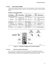
...10 N/C In/ Out Description Out Front panel green LED Out Front panel yellow LED In Power switch Ground Not connected Figure 11. Technical Reference 2.2.2.4 Front Panel Header This section describes the functions of the front panel header. Connection Diagram for Front Panel Header 2.2.2.4.1 Hard Drive Activity LED Header...11 is being read from or written to provide a visual indicator that data is a connection diagram for the front panel header. Front Panel Header Pin Signal In/ Out Description Hard Drive Activity LED 1 HD_PWR Out Hard disk LED pull-up to an ...
...10 N/C In/ Out Description Out Front panel green LED Out Front panel yellow LED In Power switch Ground Not connected Figure 11. Technical Reference 2.2.2.4 Front Panel Header This section describes the functions of the front panel header. Connection Diagram for Front Panel Header 2.2.2.4.1 Hard Drive Activity LED Header...11 is being read from or written to provide a visual indicator that data is a connection diagram for the front panel header. Front Panel Header Pin Signal In/ Out Description Hard Drive Activity LED 1 HD_PWR Out Hard disk LED pull-up to an ...
Technical Product Specification
Page 50
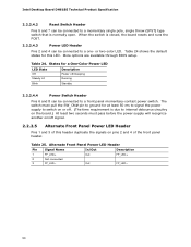
...States for a One-Color Power LED LED State Description Off Power off signal. 2.2.2.5 Alternate Front Panel Power LED Header Pins 1 and 3 of the front panel header. Alternate Front Panel Power LED Header Pin Signal Name In/Out Description 1 FP_LED+ Out FP_LED+ 2 Not connected...Steady Lit Running Blink Standby 2.2.2.4.4 Power Switch Header Pins 6 and 8 can be connected to a front panel momentary-contact power switch. or two-color LED. Intel Desktop Board DH61BE Technical Product Specification 2.2.2.4.2 Reset Switch Header Pins 5 and 7 can be connected to a one- Table 24...
...States for a One-Color Power LED LED State Description Off Power off signal. 2.2.2.5 Alternate Front Panel Power LED Header Pins 1 and 3 of the front panel header. Alternate Front Panel Power LED Header Pin Signal Name In/Out Description 1 FP_LED+ Out FP_LED+ 2 Not connected...Steady Lit Running Blink Standby 2.2.2.4.4 Power Switch Header Pins 6 and 8 can be connected to a front panel momentary-contact power switch. or two-color LED. Intel Desktop Board DH61BE Technical Product Specification 2.2.2.4.2 Reset Switch Header Pins 5 and 7 can be connected to a one- Table 24...
Technical Product Specification
Page 51
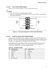
... for a description of the POST codes). Table 26. NOTE • The +5 V DC power on the USB headers is a connection diagram for the front panel USB headers. The POST card can interface with the Low Pin Count (LPC) Debug header. Connection Diagram for determining the point where an error occurred... I/O port 80h. This code is left at port 80h. If the POST fails, execution stops and the last POST code generated is useful for Front Panel USB Headers 2.2.2.7 Low Pin Count (LPC) Debug Header During the POST, the BIOS generates diagnostic progress codes (POST codes) to Section 4.5 on a ...
... for a description of the POST codes). Table 26. NOTE • The +5 V DC power on the USB headers is a connection diagram for the front panel USB headers. The POST card can interface with the Low Pin Count (LPC) Debug header. Connection Diagram for determining the point where an error occurred... I/O port 80h. This code is left at port 80h. If the POST fails, execution stops and the last POST code generated is useful for Front Panel USB Headers 2.2.2.7 Low Pin Count (LPC) Debug Header During the POST, the BIOS generates diagnostic progress codes (POST codes) to Section 4.5 on a ...


