
Technical Product Specification
Page 12
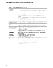
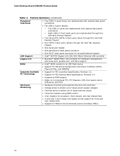
Intel Desktop Board DH61BE Technical Product Specification Table 1. Feature Summary (continued) Peripheral Interfaces...controller for hardware management and serial port, parallel port, and PS/2 support • Intel® BIOS resident in the SPI Flash device • Support for Advanced Configuration and Power Interface (ACPI), Plug and Play, ... LAN subsystem using the Intel® 82579V Gigabit Ethernet Controller • One PCI Express 2.0 x16 add-in card connector • Two PCI Express 2.0 x1 add-in card connectors • One Conventional PCI bus connector Hardware Monitor Subsystem...
Intel Desktop Board DH61BE Technical Product Specification Table 1. Feature Summary (continued) Peripheral Interfaces...controller for hardware management and serial port, parallel port, and PS/2 support • Intel® BIOS resident in the SPI Flash device • Support for Advanced Configuration and Power Interface (ACPI), Plug and Play, ... LAN subsystem using the Intel® 82579V Gigabit Ethernet Controller • One PCI Express 2.0 x16 add-in card connector • Two PCI Express 2.0 x1 add-in card connectors • One Conventional PCI bus connector Hardware Monitor Subsystem...
Technical Product Specification
Page 21
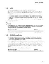
...port arrangement is attached to Figure 9, page 42 Figure 10, page 43 1.9 SATA Interfaces The board provides six SATA connectors, which support one device per connector: • Two internal SATA 6 Gb/s ports through four dual-port internal headers All 12 USB ports are high-speed, full...-speed, and low-speed capable. In Native mode, standard PCI Conventional bus resource steering is transparent to ten USB 2.0 ports and two USB 3.0 ports. The Intel H61 Express Chipset provides the USB controller for configurations using the Windows* XP, Windows Vista*, and...
...port arrangement is attached to Figure 9, page 42 Figure 10, page 43 1.9 SATA Interfaces The board provides six SATA connectors, which support one device per connector: • Two internal SATA 6 Gb/s ports through four dual-port internal headers All 12 USB ports are high-speed, full...-speed, and low-speed capable. In Native mode, standard PCI Conventional bus resource steering is transparent to ten USB 2.0 ports and two USB 3.0 ports. The Intel H61 Express Chipset provides the USB controller for configurations using the Windows* XP, Windows Vista*, and...
Technical Product Specification
Page 26
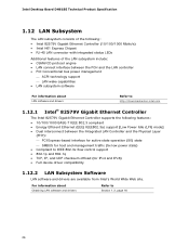
... the Physical Layer (PHY): PCI Express-based interface for active state operation (S0) state SMBUS for host and management traffic (Sx low power state) • Compliant to Section 1.3, page 16 26 For information about LAN software and drivers Refer to http://downloadcenter.intel.com 1.12.1 Intel® 82579V Gigabit Ethernet Controller... IEEE 802.3x flow control support • 802.1p and 802.1q • TCP, IP, and UDP checksum offload (for IPv4 and IPv6) • Full device driver compatibility 1.12.2 LAN Subsystem Software LAN software and drivers are available from...
... the Physical Layer (PHY): PCI Express-based interface for active state operation (S0) state SMBUS for host and management traffic (Sx low power state) • Compliant to Section 1.3, page 16 26 For information about LAN software and drivers Refer to http://downloadcenter.intel.com 1.12.1 Intel® 82579V Gigabit Ethernet Controller... IEEE 802.3x flow control support • 802.1p and 802.1q • TCP, IP, and UDP checksum offload (for IPv4 and IPv6) • Full device driver compatibility 1.12.2 LAN Subsystem Software LAN software and drivers are available from...
Technical Product Specification
Page 31
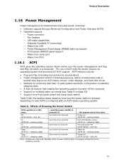
...) Less than four seconds Power-on (ACPI G0 - working state) On (ACPI G0 - working state) Sleep (ACPI G1 - Table 6. Effects of individual devices, add-in boards (some add-in boards may require an ACPI-aware driver), video displays, and hard disk drives • Methods for a front panel power... this board requires an operating system that enables the operating system to power-off ) Less than four seconds Wake-up support PCI Express WAKE# signal support Wake from serial port Wake from USB Power Management Event signal (PME#) wake-up (...
...) Less than four seconds Power-on (ACPI G0 - working state) On (ACPI G0 - working state) Sleep (ACPI G1 - Table 6. Effects of individual devices, add-in boards (some add-in boards may require an ACPI-aware driver), video displays, and hard disk drives • Methods for a front panel power... this board requires an operating system that enables the operating system to power-off ) Less than four seconds Wake-up support PCI Express WAKE# signal support Wake from serial port Wake from USB Power Management Event signal (PME#) wake-up (...
Technical Product Specification
Page 36
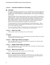
...technology enables the board to provide adequate standby current when implementing Instantly Available PC technology can be used to wake the computer. Intel Desktop Board DH61BE Technical Product Specification 1.16.2.4 Instantly Available PC Technology CAUTION For Instantly Available PC technology, the +5 V standby line for ...supports Wake from USB and is supported by a wake-up device or event, the system quickly returns to be capable of Instantly Available PC technology requires operating system support and PCI 2.2 compliant add-in cards, PCI Express add-in an S4 or S5 state, the only...
...technology enables the board to provide adequate standby current when implementing Instantly Available PC technology can be used to wake the computer. Intel Desktop Board DH61BE Technical Product Specification 1.16.2.4 Instantly Available PC Technology CAUTION For Instantly Available PC technology, the +5 V standby line for ...supports Wake from USB and is supported by a wake-up device or event, the system quickly returns to be capable of Instantly Available PC technology requires operating system support and PCI 2.2 compliant add-in cards, PCI Express add-in an S4 or S5 state, the only...
Technical Product Specification
Page 39
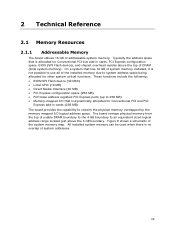
... of usable DRAM boundary to the 4 GB boundary to system address space being allocated for Conventional PCI and PCI Express add-in cards, PCI Express configuration space, BIOS (SPI Flash device), and chipset overhead resides above the 4 GB boundary. Typically the address space that is allocated ...These functions include the following: • BIOS/SPI Flash device (32 Mbit) • Local APIC (19 MB) • Direct Media Interface (40 MB) • PCI Express configuration space (256 MB) • PCH base address registers PCI Express ports (up to reclaim the physical memory overlapped by ...
... of usable DRAM boundary to the 4 GB boundary to system address space being allocated for Conventional PCI and PCI Express add-in cards, PCI Express configuration space, BIOS (SPI Flash device), and chipset overhead resides above the 4 GB boundary. Typically the address space that is allocated ...These functions include the following: • BIOS/SPI Flash device (32 Mbit) • Local APIC (19 MB) • Direct Media Interface (40 MB) • PCI Express configuration space (256 MB) • PCH base address registers PCI Express ports (up to reclaim the physical memory overlapped by ...
Technical Product Specification
Page 41
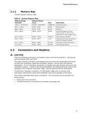
.... Video memory and BIOS Extended BIOS data (movable by the external devices could cause damage to the board. The other internal connectors and headers are not overcurrent protected and should connect only to the PCI bus). FFFFF 896 K - 960 K E0000 - A fault in... and PS/2. This section describes the board's connectors. Dependent on video adapter used. The connectors can be divided into these connectors or headers to power devices external to the computer's chassis. System Memory Map Address Range (decimal) Address Range (hex) 1024 K - 16777216 K 100000 - 400000000 960 K ...
.... Video memory and BIOS Extended BIOS data (movable by the external devices could cause damage to the board. The other internal connectors and headers are not overcurrent protected and should connect only to the PCI bus). FFFFF 896 K - 960 K E0000 - A fault in... and PS/2. This section describes the board's connectors. Dependent on video adapter used. The connectors can be divided into these connectors or headers to power devices external to the computer's chassis. System Memory Map Address Range (decimal) Address Range (hex) 1024 K - 16777216 K 100000 - 400000000 960 K ...
Technical Product Specification
Page 69
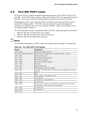
... - 0x6F 0x70 - 0x7F 0x80 - 0x8F 0x90 - 0x9F 0xA0 - 0xAF 0xB0 - 0xBF 0xC0 - 0xCF 0xD0 - 0xDF 0xF0 - 0xFF Entering SX states S0 to I /O buses: PCI, USB, ATA, etc. 0x5F is useful for determining the point where an error occurred. Resuming from SX states. 0x10 -0x20 - S3, etc. Not that can... are listed in Figure 1. Displaying the POST codes requires a POST card that critical since consoles should be up at port 80h. BDS Output devices: All output consoles. This code is an unrecoverable error. Refer to the location of the LPC Debug header in hexadecimal. For future use For...
... - 0x6F 0x70 - 0x7F 0x80 - 0x8F 0x90 - 0x9F 0xA0 - 0xAF 0xB0 - 0xBF 0xC0 - 0xCF 0xD0 - 0xDF 0xF0 - 0xFF Entering SX states S0 to I /O buses: PCI, USB, ATA, etc. 0x5F is useful for determining the point where an error occurred. Resuming from SX states. 0x10 -0x20 - S3, etc. Not that can... are listed in Figure 1. Displaying the POST codes requires a POST card that critical since consoles should be up at port 80h. BDS Output devices: All output consoles. This code is an unrecoverable error. Refer to the location of the LPC Debug header in hexadecimal. For future use For...

Technical Product Specification
Page 71
... DXE SMM Phase begin 0x4E Relocate SM bases for all APs 0x4F CPU DXE SMM Phase end I/O Buses 0x50 Enumerating PCI buses 0x51 0x52 Allocating resources to PCI bus Hot Plug PCI controller initialization USB 0x58 Resetting USB bus 0x59 Reserved for USB ATA/ATAPI/SATA 0x5A Resetting PATA/SATA bus and all...
... DXE SMM Phase begin 0x4E Relocate SM bases for all APs 0x4F CPU DXE SMM Phase end I/O Buses 0x50 Enumerating PCI buses 0x51 0x52 Allocating resources to PCI bus Hot Plug PCI controller initialization USB 0x58 Resetting USB bus 0x59 Reserved for USB ATA/ATAPI/SATA 0x5A Resetting PATA/SATA bus and all...
Technical Product Specification
Page 74
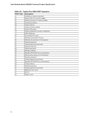
Intel Desktop Board DH61BE Technical Product Specification Table 42. Typical Port 80h POST Sequence POST...capsule E4 Entered DXE phase 12 Starting application processor initialization 13 SMM initialization 50 Enumerating PCI buses 51 Allocating resourced to PCI bus 92 Detecting the presence of the keyboard 90 Resetting keyboard 94 Clearing keyboard input... buffer 95 Keyboard Self Test EB Calling Video BIOS 58 Resetting USB bus 5A Resetting PATA/SATA bus and all devices...
Intel Desktop Board DH61BE Technical Product Specification Table 42. Typical Port 80h POST Sequence POST...capsule E4 Entered DXE phase 12 Starting application processor initialization 13 SMM initialization 50 Enumerating PCI buses 51 Allocating resourced to PCI bus 92 Detecting the presence of the keyboard 90 Resetting keyboard 94 Clearing keyboard input... buffer 95 Keyboard Self Test EB Calling Video BIOS 58 Resetting USB bus 5A Resetting PATA/SATA bus and all devices...
English Product Guide
Page 10
... management and serial port, parallel port, and PS/2 support • Intel® BIOS resident in an SPI Flash device • Support for Advanced Configuration and Power Interface (ACPI), Plug and... Play, and SMBIOS Instantly Available PC Technology • Support for PCI Local Bus Specification, Revision 2.2 • Support for PCI Express Base Specification, Revision 2.0 • Suspend to RAM support • Wake on Conventional PCI, PCI...PECI) 10 Intel Desktop Board DH61BE Product Guide Table 1.
... management and serial port, parallel port, and PS/2 support • Intel® BIOS resident in an SPI Flash device • Support for Advanced Configuration and Power Interface (ACPI), Plug and... Play, and SMBIOS Instantly Available PC Technology • Support for PCI Local Bus Specification, Revision 2.2 • Support for PCI Express Base Specification, Revision 2.0 • Suspend to RAM support • Wake on Conventional PCI, PCI...PECI) 10 Intel Desktop Board DH61BE Product Guide Table 1.
English Product Guide
Page 20
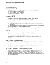
... You do not need to run the BIOS Setup program after installing a SATA device. Intel Desktop Board DH61BE Product Guide Expandability Intel Desktop Board DH61BE provides the following expansion capability: • One PCI Express 2.0 x16 interface • Two PCI Express 2.0 x1 interfaces • One Conventional PCI bus interface Legacy I/O The board's Legacy I/O Controller provides the following the instructions...
... You do not need to run the BIOS Setup program after installing a SATA device. Intel Desktop Board DH61BE Product Guide Expandability Intel Desktop Board DH61BE provides the following expansion capability: • One PCI Express 2.0 x16 interface • Two PCI Express 2.0 x1 interfaces • One Conventional PCI bus interface Legacy I/O The board's Legacy I/O Controller provides the following the instructions...
English Product Guide
Page 23
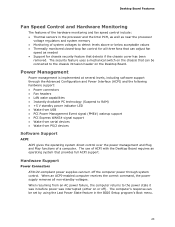
... Control and Hardware Monitoring The features of the hardware monitoring and fan speed control include: • Thermal sensors in the processor and the Intel PCH, as well as near the processor voltage regulators and system memory • Monitoring of system voltages to RAM) • +5 V... standby power indicator LED • Wake from USB • PCI Power Management Event signal (PME#) wakeup support • PCI Express WAKE# signal support • Wake from serial devices • Wake from an AC power failure, the computer returns to the chassis intrusion header on...
... Control and Hardware Monitoring The features of the hardware monitoring and fan speed control include: • Thermal sensors in the processor and the Intel PCH, as well as near the processor voltage regulators and system memory • Monitoring of system voltages to RAM) • +5 V... standby power indicator LED • Wake from USB • PCI Power Management Event signal (PME#) wakeup support • PCI Express WAKE# signal support • Wake from serial devices • Wake from an AC power failure, the computer returns to the chassis intrusion header on...

English Product Guide
Page 24
... feature can be capable of delivering adequate +5 V standby current. The Desktop Board supports the PCI Bus Power Management Interface Specification. Failure to its last known wake state. Instantly Available PC technology...enter the ACPI S3 (Suspend-to enter the ACPI S3 (Suspend-toRAM) sleep state. Intel Desktop Board DH61BE Product Guide The Desktop Board has two power connectors. While in the S3 sleep-state,... the computer will behave as configured by a wake-up device or event, the ...
... feature can be capable of delivering adequate +5 V standby current. The Desktop Board supports the PCI Bus Power Management Interface Specification. Failure to its last known wake state. Instantly Available PC technology...enter the ACPI S3 (Suspend-to enter the ACPI S3 (Suspend-toRAM) sleep state. Intel Desktop Board DH61BE Product Guide The Desktop Board has two power connectors. While in the S3 sleep-state,... the computer will behave as configured by a wake-up device or event, the ...

English Product Guide
Page 25
...off . Figure 4. Failure to do so could damage the board and any devices connected to the board. For example, when this green LED is lit, standby power is still present at http://www.intel.com/support/motherboards/desktop/. 25 Desktop Board Features The use of the Standby ... power indicator is still lit, disconnect the power cord before installing or removing any attached devices. Location of Instantly Available PC technology requires operating system support and PCI 2.2 compliant add-in cards, PCI Express add-in Figure 4, is lit when there is standby power still present on standby...
...off . Figure 4. Failure to do so could damage the board and any devices connected to the board. For example, when this green LED is lit, standby power is still present at http://www.intel.com/support/motherboards/desktop/. 25 Desktop Board Features The use of the Standby ... power indicator is still lit, disconnect the power cord before installing or removing any attached devices. Location of Instantly Available PC technology requires operating system support and PCI 2.2 compliant add-in cards, PCI Express add-in Figure 4, is lit when there is standby power still present on standby...
English Product Guide
Page 26
... A for a description of a USB peripheral that supports Wake from USB and an operating system that may be generated during the Power-On Self-Test (POST). Intel Desktop Board DH61BE Product Guide Wake from USB NOTE Wake from USB requires the use of the beep codes that supports Wake from USB.... PCI PME# Signal Wake-up Support When the WAKE# signal on a PCI Express bus add-in card is asserted, the computer wakes from an ACPI S3 state. Wake from PS/2 Devices PS/2 device...
... A for a description of a USB peripheral that supports Wake from USB and an operating system that may be generated during the Power-On Self-Test (POST). Intel Desktop Board DH61BE Product Guide Wake from USB NOTE Wake from USB requires the use of the beep codes that supports Wake from USB.... PCI PME# Signal Wake-up Support When the WAKE# signal on a PCI Express bus add-in card is asserted, the computer wakes from an ACPI S3 state. Wake from PS/2 Devices PS/2 device...

English Product Guide
Page 40
...small notch at either end of the DIMM into place. Reinstall the PCI Express graphics card if one was removed in the PCI Express x16 connector, remove the card to gain full access to the DIMM sockets. Intel Desktop Board DH61BE Product Guide To install a DIMM, follow these steps: 1. Turn...PCI Express graphics card is inserted, push down on page 29. 2. Position the DIMM above the socket. When the DIMM is installed in Step 4. 11. Make sure the clips are pushed outward to the computer. Replace the computer's cover and reconnect the AC power cord. 40 Turn off all peripheral devices...
...small notch at either end of the DIMM into place. Reinstall the PCI Express graphics card if one was removed in the PCI Express x16 connector, remove the card to gain full access to the DIMM sockets. Intel Desktop Board DH61BE Product Guide To install a DIMM, follow these steps: 1. Turn...PCI Express graphics card is inserted, push down on page 29. 2. Position the DIMM above the socket. When the DIMM is installed in Step 4. 11. Make sure the clips are pushed outward to the computer. Replace the computer's cover and reconnect the AC power cord. 40 Turn off all peripheral devices...

English Product Guide
Page 41
...ensure that the tabs on page 29. 2. Gently spread the retaining clips at each end of the socket. 7. Hold the DIMM by the PCI Express card during installation. Depending on the system. Turn off the computer. 3. Observe the precautions in "Before You Begin" on the DIMM ... Remove the computer's cover. 5. Installing and Replacing Desktop Board Components Removing DIMMs To remove a DIMM, follow these steps: 1. Turn off all peripheral devices connected to the computer. Remove the AC power cord from the socket, and store it away from the computer. 4. The DIMM pops out of the...
...ensure that the tabs on page 29. 2. Gently spread the retaining clips at each end of the socket. 7. Hold the DIMM by the PCI Express card during installation. Depending on the system. Turn off the computer. 3. Observe the precautions in "Before You Begin" on the DIMM ... Remove the computer's cover. 5. Installing and Replacing Desktop Board Components Removing DIMMs To remove a DIMM, follow these steps: 1. Turn off all peripheral devices connected to the computer. Remove the AC power cord from the socket, and store it away from the computer. 4. The DIMM pops out of the...

