
Product Guide
Page 4
... cable • One diskette drive cable • Four Serial ATA cables • One rear panel USB 2.0 adapter • One front panel USB 2.0/IEEE 1394/audio adapter • One 2x2 to some common terms used in the product guide. Intel Desktop Board D975XBX Product Guide Terminology The table below gives descriptions to 2x4 power supply cable adapter...
... cable • One diskette drive cable • Four Serial ATA cables • One rear panel USB 2.0 adapter • One front panel USB 2.0/IEEE 1394/audio adapter • One 2x2 to some common terms used in the product guide. Intel Desktop Board D975XBX Product Guide Terminology The table below gives descriptions to 2x4 power supply cable adapter...
Product Guide
Page 6
Intel Desktop Board D975XBX Product Guide Installing and Removing Memory 31 Installing DIMMs...32 Removing DIMMs...35 Installing and Removing a PCI Express x16 Card 35 Installing a PCI Express x16 Card 36 Removing the PCI Express x16 Card 37 Connecting the IDE Cable 38 Connecting the Serial ATA Cable 39 Connecting Internal Headers 40 Front Panel... Power Supply Cables 47 Other Connectors...48 Setting the BIOS Configuration Jumper 49 Clearing Passwords ...50 Back Panel Connectors...51 Replacing the Battery ...52 3 BIOS Accessing the BIOS Setup Program 57 Updating the BIOS ...57 Updating the...
Intel Desktop Board D975XBX Product Guide Installing and Removing Memory 31 Installing DIMMs...32 Removing DIMMs...35 Installing and Removing a PCI Express x16 Card 35 Installing a PCI Express x16 Card 36 Removing the PCI Express x16 Card 37 Connecting the IDE Cable 38 Connecting the Serial ATA Cable 39 Connecting Internal Headers 40 Front Panel... Power Supply Cables 47 Other Connectors...48 Setting the BIOS Configuration Jumper 49 Clearing Passwords ...50 Back Panel Connectors...51 Replacing the Battery ...52 3 BIOS Accessing the BIOS Setup Program 57 Updating the BIOS ...57 Updating the...

Product Guide
Page 7
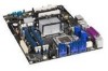
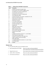
Location of Fan Headers 45 26. Remove the Protective Socket Cover 28 9. Desktop Board D975XBX Components 11 2. Install the Processor ...29 11. Dual Channel Memory Configuration Example 1 31 14. Installing a DIMM ...34 18. Connecting the Rear Panel USB 2.0 Adapter 43 24. LAN Connector LEDs...16 3. Dual Channel Memory Configuration Example 3 32 16. Use DDR2 DIMMs...
Location of Fan Headers 45 26. Remove the Protective Socket Cover 28 9. Desktop Board D975XBX Components 11 2. Install the Processor ...29 11. Dual Channel Memory Configuration Example 1 31 14. Installing a DIMM ...34 18. Connecting the Rear Panel USB 2.0 Adapter 43 24. LAN Connector LEDs...16 3. Dual Channel Memory Configuration Example 3 32 16. Use DDR2 DIMMs...

Product Guide
Page 10
... back panel ⎯ Four ports routed to : http://support.intel.com/support/motherboards/desktop/ Supported Operating Systems The desktop board supports the following operating systems: • Microsoft Windows* XP Media Center Edition 2005 • Microsoft Windows XP Professional • Microsoft Windows XP Professional x64 Edition • Microsoft Windows XP Home • Microsoft Windows 2000 10 Intel Desktop Board D975XBX Product...
... back panel ⎯ Four ports routed to : http://support.intel.com/support/motherboards/desktop/ Supported Operating Systems The desktop board supports the following operating systems: • Microsoft Windows* XP Media Center Edition 2005 • Microsoft Windows XP Professional • Microsoft Windows XP Professional x64 Edition • Microsoft Windows XP Home • Microsoft Windows 2000 10 Intel Desktop Board D975XBX Product...
Product Guide
Page 12
.../s Serial ATA connectors 4, 5, 6, and 7 (blue) Front panel header Speaker Related Links Go to the following links for more information about: • Intel Desktop Board D975XBX http://www.intel.com/design/motherbd http://support.intel.com/support/motherboards/desktop • Supported processors http://support.intel.com/support/motherboards/desktop • Audio software and utilities http://www.intel.com/design/motherbd • LAN software and...
.../s Serial ATA connectors 4, 5, 6, and 7 (blue) Front panel header Speaker Related Links Go to the following links for more information about: • Intel Desktop Board D975XBX http://www.intel.com/design/motherbd http://support.intel.com/support/motherboards/desktop • Supported processors http://support.intel.com/support/motherboards/desktop • Audio software and utilities http://www.intel.com/design/motherbd • LAN software and...

Product Guide
Page 14
Intel Desktop Board D975XBX Product Guide Related Links Go to the following links or pages for more information about: • The latest list of tested memory, http://support.intel.com/support/motherboards/desktop/ • SDRAM specifications, http://www.intel.com/technology/memory/ • Installing memory, page 31 in Chapter 2 Intel® 975X Express Chipset The Intel... The subsystem includes the following connectors: • Front panel audio connector, including pins for: ⎯ Line out ⎯ Mic • Back panel audio connectors that are configurable through the drivers of the...
Intel Desktop Board D975XBX Product Guide Related Links Go to the following links or pages for more information about: • The latest list of tested memory, http://support.intel.com/support/motherboards/desktop/ • SDRAM specifications, http://www.intel.com/technology/memory/ • Installing memory, page 31 in Chapter 2 Intel® 975X Express Chipset The Intel... The subsystem includes the following connectors: • Front panel audio connector, including pins for: ⎯ Line out ⎯ Mic • Back panel audio connectors that are configurable through the drivers of the...

Product Guide
Page 15
Desktop Board Features Related Links Go to the D975XBX link on Intel's World Wide Web site at: http://support.intel.com/support/motherboards/desktop 15 The LAN subsystem provides the following functions: • Intel 82573V or 82573L Ethernet LAN supporting 10/100/1000 Mbit/sec • ...refer to the following link or pages for more information about: • Audio drivers and utilities http://support.intel.com/support/motherboards/desktop/ • Installing the front panel audio adapter, page 44 in Chapter 2 Input/Output (I/O) Controller The super I/O controller features the following: ...
Desktop Board Features Related Links Go to the D975XBX link on Intel's World Wide Web site at: http://support.intel.com/support/motherboards/desktop 15 The LAN subsystem provides the following functions: • Intel 82573V or 82573L Ethernet LAN supporting 10/100/1000 Mbit/sec • ...refer to the following link or pages for more information about: • Audio drivers and utilities http://support.intel.com/support/motherboards/desktop/ • Installing the front panel audio adapter, page 44 in Chapter 2 Input/Output (I/O) Controller The super I/O controller features the following: ...

Product Guide
Page 16
... are built into the RJ-45 LAN connector located on the back panel (see Figure 2). The desktop board supports up and the 10/100/1000 Gigabit Ethernet LAN subsystem is powered up to accommodate operating systems that fully support USB 2.0 transfer rates. Intel Desktop Board D975XBX Product Guide RJ-45 LAN Connector LEDs Two LEDs are backward...
... are built into the RJ-45 LAN connector located on the back panel (see Figure 2). The desktop board supports up and the 10/100/1000 Gigabit Ethernet LAN subsystem is powered up to accommodate operating systems that fully support USB 2.0 transfer rates. Intel Desktop Board D975XBX Product Guide RJ-45 LAN Connector LEDs Two LEDs are backward...

Product Guide
Page 19
...; Precision Cooling Technology) Intel Precision Cooling Technology automatically adjusts the processor fan speed based on the processor temperature and adjusts the chassis fan speeds depending on the front panel, the sleep state is attached to provide adequate standby current when using...to support multiple wake events from the PCI and/or USB buses exceeds power supply capacity, the desktop board may be disabled independently through the desktop board BIOS. Fan Connectors Desktop Board D975XBX has three chassis fan connectors (two 3-pin and one 4-pin) and one processor fan connector ...
...; Precision Cooling Technology) Intel Precision Cooling Technology automatically adjusts the processor fan speed based on the processor temperature and adjusts the chassis fan speeds depending on the front panel, the sleep state is attached to provide adequate standby current when using...to support multiple wake events from the PCI and/or USB buses exceeds power supply capacity, the desktop board may be disabled independently through the desktop board BIOS. Fan Connectors Desktop Board D975XBX has three chassis fan connectors (two 3-pin and one 4-pin) and one processor fan connector ...

Product Guide
Page 23
... and remove the desktop board • Install and remove a processor • Install and remove memory • Install and remove a PCI Express x16 add-in card • Connect the IDE and Serial ATA cables • Connect internal headers • Install the rear and front panel USB/IEEE 1394/audio...to a metal part of the procedures described in personal injury or equipment damage. Some circuitry on the board can damage components. Failure to operate even though the front panel power button is not available, you can result in this chapter. Follow these guidelines before you begin:...
... and remove the desktop board • Install and remove a processor • Install and remove memory • Install and remove a PCI Express x16 add-in card • Connect the IDE and Serial ATA cables • Connect internal headers • Install the rear and front panel USB/IEEE 1394/audio...to a metal part of the procedures described in personal injury or equipment damage. Some circuitry on the board can damage components. Failure to operate even though the front panel power button is not available, you can result in this chapter. Follow these guidelines before you begin:...

Product Guide
Page 36
... page 23. 2. B A OM18187 Figure 18. Follow these instructions to the chassis back panel with a screw. However, if you are installing two PCI Express Graphics cards, install them in PCI Express connectors 1 and 2 (see Figure 18, A) for optimum performance. Intel Desktop Board D975XBX Product Guide Installing a PCI Express x16 Card If you are installing a single PCI...
... page 23. 2. B A OM18187 Figure 18. Follow these instructions to the chassis back panel with a screw. However, if you are installing two PCI Express Graphics cards, install them in PCI Express connectors 1 and 2 (see Figure 18, A) for optimum performance. Intel Desktop Board D975XBX Product Guide Installing a PCI Express x16 Card If you are installing a single PCI...

Product Guide
Page 37
A C B Figure 19. Remove the screw that secures the card's metal bracket to remove the PCI Express x16 card from the RM: 1. Pull the card straight up (Figure 19, C). Push down on the RM lever until the retention pin completely clears the notch in "Before You Begin" on page 23. 2. Observe the precautions in the card (Figure 19, B). 4. Removing the PCI Express x16 Card OM18188 37 Installing and Replacing Desktop Board Components Removing the PCI Express x16 Card Follow these instructions to the chassis back panel (Figure 19, A). 3.
A C B Figure 19. Remove the screw that secures the card's metal bracket to remove the PCI Express x16 card from the RM: 1. Pull the card straight up (Figure 19, C). Push down on the RM lever until the retention pin completely clears the notch in "Before You Begin" on page 23. 2. Observe the precautions in the card (Figure 19, B). 4. Removing the PCI Express x16 Card OM18188 37 Installing and Replacing Desktop Board Components Removing the PCI Express x16 Card Follow these instructions to the chassis back panel (Figure 19, A). 3.

Product Guide
Page 40
...5 6 TPA2- +12 V 7 8 +12 V Key (no pin) 10 No Connection Item A B C D E Description Front panel audio USB 2.0 IEEE 1394a Alternate front panel power LED Front panel Figure 22. Internal Headers OM18191 40 Intel Desktop Board D975XBX Product Guide Connecting Internal Headers Before connecting cables to the internal headers, observe the precautions in "Before You Begin" on... 1 2 Power (+5 V) D- 3 4 D- HD LED + A Port1L 1 2 GND Port1R 3 4 Presence# Port2R 5 6 Sense1_Ret Sense_Send 7 Key (no pin) Port2L 9 10 Sense2_Ret D -3 +1 Alternate Front Panel Power LED C TPA1+ 1 2 TPA1-
...5 6 TPA2- +12 V 7 8 +12 V Key (no pin) 10 No Connection Item A B C D E Description Front panel audio USB 2.0 IEEE 1394a Alternate front panel power LED Front panel Figure 22. Internal Headers OM18191 40 Intel Desktop Board D975XBX Product Guide Connecting Internal Headers Before connecting cables to the internal headers, observe the precautions in "Before You Begin" on... 1 2 Power (+5 V) D- 3 4 D- HD LED + A Port1L 1 2 GND Port1R 3 4 Presence# Port2R 5 6 Sense1_Ret Sense_Send 7 Key (no pin) Port2L 9 10 Sense2_Ret D -3 +1 Alternate Front Panel Power LED C TPA1+ 1 2 TPA1-

Product Guide
Page 41
...connect 41 Table 7 shows the pin assignments for the header. Table 5 shows the pin assignments for the location of the yellow front panel audio header. Front Panel Audio Header Signal Names Pin Signal Name 1 Port1L 3 Port1R 5 Port2R 7 Sense Send 9 Port2L Pin Signal Name 2 GND 4...Ground 4 5 TPA2+ 6 7 +12 V 8 9 Key (no pin) 10 Sense2 Ret IEEE 1394a Header See Figure 22, C for the front panel audio header. Installing and Replacing Desktop Board Components Front Panel Audio Header Figure 22, A on page 40 shows the location of the blue IEEE 1394a header.
...connect 41 Table 7 shows the pin assignments for the header. Table 5 shows the pin assignments for the location of the yellow front panel audio header. Front Panel Audio Header Signal Names Pin Signal Name 1 Port1L 3 Port1R 5 Port2R 7 Sense Send 9 Port2L Pin Signal Name 2 GND 4...Ground 4 5 TPA2+ 6 7 +12 V 8 9 Key (no pin) 10 Sense2 Ret IEEE 1394a Header See Figure 22, C for the front panel audio header. Installing and Replacing Desktop Board Components Front Panel Audio Header Figure 22, A on page 40 shows the location of the blue IEEE 1394a header.

Product Guide
Page 42
... Activity LED (Yellow) Power LED (Green) 1 HD_PWR Out Hard disk LED pull- 2 HDR_BLNK_GRN Out Front panel green up (330 Ω) to this header. 42 Intel Desktop Board D975XBX Product Guide Front Panel Header Figure 22, E on page 40 shows the location of the multi-colored front... panel header. Table 8. Table 8 shows the pin assignments for the front panel header. If you have a three-pin power LED cable, ...
... Activity LED (Yellow) Power LED (Green) 1 HD_PWR Out Hard disk LED pull- 2 HDR_BLNK_GRN Out Front panel green up (330 Ω) to this header. 42 Intel Desktop Board D975XBX Product Guide Front Panel Header Figure 22, E on page 40 shows the location of the multi-colored front... panel header. Table 8. Table 8 shows the pin assignments for the front panel header. If you have a three-pin power LED cable, ...

Product Guide
Page 43
Attach the cable end with a screw. Installing and Replacing Desktop Board Components Installing the Rear Panel USB 2.0 Adapter Follow these instructions to the chassis back panel with the connector to the USB 2.0 header on page 23. 2. Secure the cable's metal bracket to install the rear panel USB 2.0 adapter (see Figure 23): 1. Connecting the Rear Panel USB 2.0 Adapter OM18192 43 Observe the precautions in "Before You Begin" on the desktop board. 3. Figure 23.
Attach the cable end with a screw. Installing and Replacing Desktop Board Components Installing the Rear Panel USB 2.0 Adapter Follow these instructions to the chassis back panel with the connector to the USB 2.0 header on page 23. 2. Secure the cable's metal bracket to install the rear panel USB 2.0 adapter (see Figure 23): 1. Connecting the Rear Panel USB 2.0 Adapter OM18192 43 Observe the precautions in "Before You Begin" on the desktop board. 3. Figure 23.

Product Guide
Page 44
... AC power cord. 3. Remove the cover. 4. Remove the front panel USB/IEEE 1394/audio adapter cables. 5. Intel Desktop Board D975XBX Product Guide Installing the Front Panel USB/IEEE 1394/Audio Adapter To install the front panel USB/IEEE 1394/audio adapter cables to their respective headers on the desktop board. 7. Turn off all peripheral devices connected to the computer...
... AC power cord. 3. Remove the cover. 4. Remove the front panel USB/IEEE 1394/audio adapter cables. 5. Intel Desktop Board D975XBX Product Guide Installing the Front Panel USB/IEEE 1394/Audio Adapter To install the front panel USB/IEEE 1394/audio adapter cables to their respective headers on the desktop board. 7. Turn off all peripheral devices connected to the computer...

Product Guide
Page 51
Installing and Replacing Desktop Board Components Back Panel Connectors NOTE The line out connector, located on the back panel, is designed to this output. Figure 30 shows the back panel connectors. RJ45 IEEE 1394 Line In Coaxial Digital Line Out Optical Digital Line Out (Toslink) Figure 30. Back Panel Connectors OM18200 51 Poor audio quality may occur if passive (non-amplified) speakers are connected to power either headphones or amplified speakers only.
Installing and Replacing Desktop Board Components Back Panel Connectors NOTE The line out connector, located on the back panel, is designed to this output. Figure 30 shows the back panel connectors. RJ45 IEEE 1394 Line In Coaxial Digital Line Out Optical Digital Line Out (Toslink) Figure 30. Back Panel Connectors OM18200 51 Poor audio quality may occur if passive (non-amplified) speakers are connected to power either headphones or amplified speakers only.

Product Guide
Page 63
... http://support.intel.com/support/motherboards/desktop/. 5 Intel® Quick Resume Technology Driver (Intel® QRTD) Overview The Intel® Quick Resume Technology Driver manages the on and off functions for the display to be set . After the Intel Quick Resume Technology Driver is displayed. 63 Opening the chassis in the background. • Works with the desktop board or...
... http://support.intel.com/support/motherboards/desktop/. 5 Intel® Quick Resume Technology Driver (Intel® QRTD) Overview The Intel® Quick Resume Technology Driver manages the on and off functions for the display to be set . After the Intel Quick Resume Technology Driver is displayed. 63 Opening the chassis in the background. • Works with the desktop board or...


