Product Guide
Page 4
Intel Desktop Board D945GCNL Product Guide Terminology The table below gives descriptions of some common terms used in the product guide. Term Description GB Gigabyte (1,073,741,824 bytes) ... (one billion hertz) KB Kilobyte (1024 bytes) MB Megabyte (1,048,576 bytes) Mbit Megabit (1,048,576 bits) MHz Megahertz (one million hertz) Box Contents • Intel Desktop Board D945GCNL • I/O shield • One diskette drive cable • One ATA-66/100 cable • Two locking Serial ATA cables •...
Intel Desktop Board D945GCNL Product Guide Terminology The table below gives descriptions of some common terms used in the product guide. Term Description GB Gigabyte (1,073,741,824 bytes) ... (one billion hertz) KB Kilobyte (1024 bytes) MB Megabyte (1,048,576 bytes) Mbit Megabit (1,048,576 bits) MHz Megahertz (one million hertz) Box Contents • Intel Desktop Board D945GCNL • I/O shield • One diskette drive cable • One ATA-66/100 cable • Two locking Serial ATA cables •...
Product Guide
Page 5
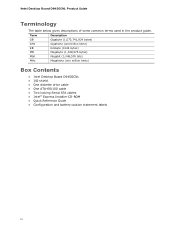
Contents 1 Desktop Board Features Supported Operating Systems 10 Desktop Board Components 11 Processor ...13 Main Memory...13 Intel® 945GC Express Chipset 14 Onboard Audio Subsystem 14 Input/Output (I/O) Controller 15 LAN Subsystem 15...Battery ...22 Real-Time Clock 22 2 Installing and Replacing Desktop Board Components Before You Begin 23 Installation Precautions 24 Prevent Power Supply Overload 24 Observe Safety and Regulatory Requirements 24 Installing the I/O Shield 25 Installing and Removing the Desktop Board 26 Installing and Removing a Processor 27 Installing a Processor...
Contents 1 Desktop Board Features Supported Operating Systems 10 Desktop Board Components 11 Processor ...13 Main Memory...13 Intel® 945GC Express Chipset 14 Onboard Audio Subsystem 14 Input/Output (I/O) Controller 15 LAN Subsystem 15...Battery ...22 Real-Time Clock 22 2 Installing and Replacing Desktop Board Components Before You Begin 23 Installation Precautions 24 Prevent Power Supply Overload 24 Observe Safety and Regulatory Requirements 24 Installing the I/O Shield 25 Installing and Removing the Desktop Board 26 Installing and Removing a Processor 27 Installing a Processor...

Product Guide
Page 7
.... Contents Figures 1. Desktop Board D945GCNL Components 11 2. Remove the Processor from the Protective Processor Cover 29 10. Dual Channel Memory Configuration Example 32 14. Removing a PCI Express x16 Card 37 18. Lead-Free Board Markings 64 14. Install the Processor 29 11. Back Panel Audio Connectors 43 22. Feature Summary 9 2. Installing the I/O Shield 25 5. Product...
.... Contents Figures 1. Desktop Board D945GCNL Components 11 2. Remove the Processor from the Protective Processor Cover 29 10. Dual Channel Memory Configuration Example 32 14. Removing a PCI Express x16 Card 37 18. Lead-Free Board Markings 64 14. Install the Processor 29 11. Back Panel Audio Connectors 43 22. Feature Summary 9 2. Installing the I/O Shield 25 5. Product...
Product Guide
Page 16
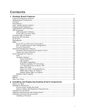
...system and drivers that meets the requirements for a full-speed USB device. USB 1.1 devices will function normally at USB 1.1 speeds. The desktop board supports up and the LAN subsystem is operating. Disabling Hi-Speed USB in the BIOS reverts all USB 2.0 ports to accommodate operating systems ... powered up to eight USB 2.0 ports via ICH7 (four ports routed to the back panel and four ports routed to the cable. Intel Desktop Board D945GCNL Product Guide RJ-45 LAN Connector LEDs Two LEDs are backward compatible with USB 1.1 devices. LAN Connector LEDs Table 3 describes the LED...
...system and drivers that meets the requirements for a full-speed USB device. USB 1.1 devices will function normally at USB 1.1 speeds. The desktop board supports up and the LAN subsystem is operating. Disabling Hi-Speed USB in the BIOS reverts all USB 2.0 ports to accommodate operating systems ... powered up to eight USB 2.0 ports via ICH7 (four ports routed to the back panel and four ports routed to the cable. Intel Desktop Board D945GCNL Product Guide RJ-45 LAN Connector LEDs Two LEDs are backward compatible with USB 1.1 devices. LAN Connector LEDs Table 3 describes the LED...

Product Guide
Page 23
Some circuitry on the board can damage components. Follow these guidelines before you begin: • Always follow the steps in each procedure in the correct order. • Set up a log ..., or modems before you open the computer or perform any of the computer chassis. 23 2 Installing and Replacing Desktop Board Components This chapter tells you how to: • Install the I/O shield • Install and remove the desktop board • Install and remove a processor • Install and remove memory • Install and remove a PCI Express x16...
Some circuitry on the board can damage components. Follow these guidelines before you begin: • Always follow the steps in each procedure in the correct order. • Set up a log ..., or modems before you open the computer or perform any of the computer chassis. 23 2 Installing and Replacing Desktop Board Components This chapter tells you how to: • Install the I/O shield • Install and remove the desktop board • Install and remove a processor • Install and remove memory • Install and remove a PCI Express x16...

Product Guide
Page 25
... shield into place so that it fits tightly and securely. If the shield does not fit, obtain a properly sized shield from dust and foreign objects, and promotes correct airflow within the chassis. Install the I /O Shield 25 Installing the I /O shield before installing the desktop board in Figure 4. Figure 4. Installing and Replacing Desktop Board Components Installing the I/O Shield The desktop board comes with an I/O shield...
... shield into place so that it fits tightly and securely. If the shield does not fit, obtain a properly sized shield from dust and foreign objects, and promotes correct airflow within the chassis. Install the I /O Shield 25 Installing the I /O shield before installing the desktop board in Figure 4. Figure 4. Installing and Replacing Desktop Board Components Installing the I/O Shield The desktop board comes with an I/O shield...
Product Guide
Page 41
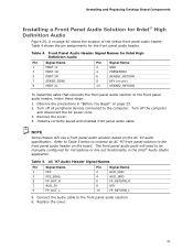
Install a correctly keyed and shielded front panel audio cable. The front panel audio jacks will need to be manually configured for Intel High Definition Audio Pin Signal Name 1 PORT 1L 3 PORT 1R 5 PORT 2R 7 SENSE_SEND 9 PORT 2L Pin Signal Name 2 GND 4 ...follow these steps: 1. Remove the cover. 4. Connect the audio cable to the computer. Table 4. Installing and Replacing Desktop Board Components Installing a Front Panel Audio Solution for Intel® High Definition Audio Figure 20, A on the AC '97 audio specification. Front Panel Audio Header Signal Names...
Install a correctly keyed and shielded front panel audio cable. The front panel audio jacks will need to be manually configured for Intel High Definition Audio Pin Signal Name 1 PORT 1L 3 PORT 1R 5 PORT 2R 7 SENSE_SEND 9 PORT 2L Pin Signal Name 2 GND 4 ...follow these steps: 1. Remove the cover. 4. Connect the audio cable to the computer. Table 4. Installing and Replacing Desktop Board Components Installing a Front Panel Audio Solution for Intel® High Definition Audio Figure 20, A on the AC '97 audio specification. Front Panel Audio Header Signal Names...

Product Guide
Page 66
Intel Desktop Board D945GCNL Product Guide Korean Class B statement translation: This is household equipment that the power supply and other non-residential environments. Pay close attention to comply with ... following when reading the installation instructions for the host chassis, power supply, and other modules: • Product certifications or lack of certifications • External I/O cable shielding and filtering • Mounting, grounding, and bonding requirements • Keying connectors when mating the wrong connectors could be hazardous If the power supply and other...
Intel Desktop Board D945GCNL Product Guide Korean Class B statement translation: This is household equipment that the power supply and other non-residential environments. Pay close attention to comply with ... following when reading the installation instructions for the host chassis, power supply, and other modules: • Product certifications or lack of certifications • External I/O cable shielding and filtering • Mounting, grounding, and bonding requirements • Keying connectors when mating the wrong connectors could be hazardous If the power supply and other...
Product Specification
Page 20
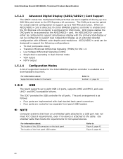
... simultaneous display with the primary VGA display or can be accessed by the ADD2/ADD2+ card. Use shielded cable that meets the requirements for the Intel GMA950 graphics controller is attached to the cable. ADD2/ADD2+ cards can be paired for all ports..... and EHCI-compatible drivers. The port arrangement is configured for the board Refer to Section 1.2, page 15 1.5.2 USB The board supports up to a 200 MHz pixel clock to the PCI Express x16 connector. Intel Desktop Board D945GCNL Technical Product Specification 1.5.1.3 Advanced Digital Display (ADD2/ADD2+) Card Support ...
... simultaneous display with the primary VGA display or can be accessed by the ADD2/ADD2+ card. Use shielded cable that meets the requirements for the Intel GMA950 graphics controller is attached to the cable. ADD2/ADD2+ cards can be paired for all ports..... and EHCI-compatible drivers. The port arrangement is configured for the board Refer to Section 1.2, page 15 1.5.2 USB The board supports up to a 200 MHz pixel clock to the PCI Express x16 connector. Intel Desktop Board D945GCNL Technical Product Specification 1.5.1.3 Advanced Digital Display (ADD2/ADD2+) Card Support ...