Product Guide
Page 5
Contents 1 Desktop Board Features Supported Operating Systems 10 Desktop Board Components 11 Processor ...13 Main Memory...13 Intel® 945GC Express Chipset 14 Onboard Audio Subsystem 14 Input/Output (I/O) Controller 15 LAN Subsystem 15 LAN Subsystem Software 15 RJ-45 LAN Connector LEDs 16 Hi-Speed USB 2.0 Support 16 Enhanced IDE Interface 17 Serial ATA...17 Expandability...17 BIOS...
Contents 1 Desktop Board Features Supported Operating Systems 10 Desktop Board Components 11 Processor ...13 Main Memory...13 Intel® 945GC Express Chipset 14 Onboard Audio Subsystem 14 Input/Output (I/O) Controller 15 LAN Subsystem 15 LAN Subsystem Software 15 RJ-45 LAN Connector LEDs 16 Hi-Speed USB 2.0 Support 16 Enhanced IDE Interface 17 Serial ATA...17 Expandability...17 BIOS...

Product Guide
Page 7
... DIMMs 33 15. Removing a PCI Express x16 Card 37 18. Connecting the Serial ATA Cable 39 20. Jumper Settings for Intel High Definition Audio 41 5. Product Certification Markings 67 vii Remove the Protective Socket Cover 28 9. Close the Load Plate 30 12...11. Safety Standards 59 13. Connecting the IDE Cable 38 19. Internal Headers 40 21. Desktop Board D945GCNL Components 12 3. BIOS Error Messages 57 12. EMC Regulations 65 15. Desktop Board D945GCNL Components 11 2. LAN Connector LEDs 16 3. Location of Chassis Fan Headers 44 23. USB 2.0 Header Signal Names...
... DIMMs 33 15. Removing a PCI Express x16 Card 37 18. Connecting the Serial ATA Cable 39 20. Jumper Settings for Intel High Definition Audio 41 5. Product Certification Markings 67 vii Remove the Protective Socket Cover 28 9. Close the Load Plate 30 12...11. Safety Standards 59 13. Connecting the IDE Cable 38 19. Internal Headers 40 21. Desktop Board D945GCNL Components 12 3. BIOS Error Messages 57 12. EMC Regulations 65 15. Desktop Board D945GCNL Components 11 2. LAN Connector LEDs 16 3. Location of Chassis Fan Headers 44 23. USB 2.0 Header Signal Names...
Product Guide
Page 10
Intel Desktop Board D945GCNL Product Guide Table 1. Feature Summary (continued) LAN Support BIOS 10/100/1000 Mb/s LAN subsystem using a Realtek RTL8111B-GR Gigabit Ethernet Controller • Intel® BIOS (resident in the SPI Flash device) • Support... • Intel® Precision Cooling Technology Related Links: For more information about Desktop Board D945GCNL, including the Technical Product Specification (TPS), BIOS updates, and device drivers, go to: http://support.intel.com/support/motherboards/desktop/ Supported Operating Systems The desktop board supports the following...
Intel Desktop Board D945GCNL Product Guide Table 1. Feature Summary (continued) LAN Support BIOS 10/100/1000 Mb/s LAN subsystem using a Realtek RTL8111B-GR Gigabit Ethernet Controller • Intel® BIOS (resident in the SPI Flash device) • Support... • Intel® Precision Cooling Technology Related Links: For more information about Desktop Board D945GCNL, including the Technical Product Specification (TPS), BIOS updates, and device drivers, go to: http://support.intel.com/support/motherboards/desktop/ Supported Operating Systems The desktop board supports the following...
Product Guide
Page 12
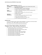
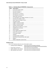
Intel Desktop Board D945GCNL Product Guide Table 2. Desktop Board D945GCNL Components Label A B C D E F G H I J K L M N O P Q R S T U V W X Description Front panel audio header PCI bus connector 2 PCI bus connector 1 PCI Express x1 ... more information about: • Desktop Board D945GCNL • Supported processors • Audio software and utilities • LAN software and drivers http://www.intel.com/design/motherbd http://support.intel.com/support/motherboards/desktop http://www.intel.com/go/FindCPU http://www.intel.com/design/motherbd http://www.intel.com/design/motherbd 12
Intel Desktop Board D945GCNL Product Guide Table 2. Desktop Board D945GCNL Components Label A B C D E F G H I J K L M N O P Q R S T U V W X Description Front panel audio header PCI bus connector 2 PCI bus connector 1 PCI Express x1 ... more information about: • Desktop Board D945GCNL • Supported processors • Audio software and utilities • LAN software and drivers http://www.intel.com/design/motherbd http://support.intel.com/support/motherboards/desktop http://www.intel.com/go/FindCPU http://www.intel.com/design/motherbd http://www.intel.com/design/motherbd 12
Product Guide
Page 15
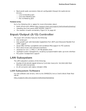
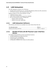
... LAN Subsystem The LAN subsystem consists of the following: • Realtek RTL811B-GR Gigabit Ethernet Controller device for 10/100/1000 Mb/s Ethernet LAN connectivity • RJ-45 connector with status indicator LEDs LAN Subsystem Software For LAN software and drivers, refer to the D945GCNL link on Intel's World Wide Web site at: http://support.intel.com/support/motherboards/desktop...
... LAN Subsystem The LAN subsystem consists of the following: • Realtek RTL811B-GR Gigabit Ethernet Controller device for 10/100/1000 Mb/s Ethernet LAN connectivity • RJ-45 connector with status indicator LEDs LAN Subsystem Software For LAN software and drivers, refer to the D945GCNL link on Intel's World Wide Web site at: http://support.intel.com/support/motherboards/desktop...
Product Guide
Page 16
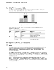
Intel Desktop Board D945GCNL Product Guide RJ-45 LAN Connector LEDs Two LEDs are backward compatible with USB 1.1 devices. These LEDs indicate the status of the LAN. USB 2.0 ports are built into the RJ-45 LAN connector located on the back panel (see Figure 2). LAN Connector LEDs Table 3 describes the LED states when the board... USB 2.0 transfer rates. USB 1.1 devices will function normally at USB 1.1 speeds. Table 3. The desktop board supports up and the LAN subsystem is attached to USB 1.1 operation. This may be required to two internal USB 2.0 headers). Figure 2.
Intel Desktop Board D945GCNL Product Guide RJ-45 LAN Connector LEDs Two LEDs are backward compatible with USB 1.1 devices. These LEDs indicate the status of the LAN. USB 2.0 ports are built into the RJ-45 LAN connector located on the back panel (see Figure 2). LAN Connector LEDs Table 3 describes the LED states when the board... USB 2.0 transfer rates. USB 1.1 devices will function normally at USB 1.1 speeds. Table 3. The desktop board supports up and the LAN subsystem is attached to USB 1.1 operation. This may be required to two internal USB 2.0 headers). Figure 2.

Product Guide
Page 19
...Fan headers ― LAN wake capabilities ― Instantly Available PC technology (Suspend to RAM) ― +5 V standby power indicator LED ― Wake from USB ― Wake from an AC power failure, the computer returns to the power state it was interrupted (either on the desktop board. See Figure 23 ...up support ACPI ACPI gives the operating system direct control over the power management and Plug and Play functions of ACPI with the desktop board requires an operating system that provides full ACPI support. The security feature uses a mechanical switch on the chassis that detects if ...
...Fan headers ― LAN wake capabilities ― Instantly Available PC technology (Suspend to RAM) ― +5 V standby power indicator LED ― Wake from USB ― Wake from an AC power failure, the computer returns to the power state it was interrupted (either on the desktop board. See Figure 23 ...up support ACPI ACPI gives the operating system direct control over the power management and Plug and Play functions of ACPI with the desktop board requires an operating system that provides full ACPI support. The security feature uses a mechanical switch on the chassis that detects if ...
Product Guide
Page 20
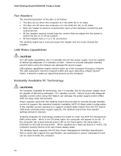
...is in memory. When signaled by the LED turning amber. Intel Desktop Board D945GCNL Product Guide Fan Headers The function/operation of the fans is as needed. • All fan headers have a +12 V dc connection. LAN wakeup capabilities enable remote wake-up signal that support this feature...up device or event, the computer quickly returns to provide adequate standby current when using this desktop board must be capable of delivering adequate +5 V standby current. LAN Wake Capabilities CAUTION For LAN wake capabilities, the 5 V standby line for the power supply must be able to ...
...is in memory. When signaled by the LED turning amber. Intel Desktop Board D945GCNL Product Guide Fan Headers The function/operation of the fans is as needed. • All fan headers have a +12 V dc connection. LAN wakeup capabilities enable remote wake-up signal that support this feature...up device or event, the computer quickly returns to provide adequate standby current when using this desktop board must be capable of delivering adequate +5 V standby current. LAN Wake Capabilities CAUTION For LAN wake capabilities, the 5 V standby line for the power supply must be able to ...

Product Specification
Page 5
...1 Product Description 1.1 Overview 10 1.1.1 Feature Summary 10 1.1.2 Board Layout 12 1.1.3 Block Diagram 14 1.2 Online Support 15 1.3 Processor 15 1.4 System Memory 16 1.4.1 Memory Configurations 17 1.5 Intel® 945GC Chipset 18 1.5.1 Intel 945GC Graphics Subsystem 18 1.5.2 USB 20 1.5.3 IDE Support 21... Subsystem 24 1.8.1 Audio Subsystem Software 24 1.8.2 Audio Connectors 24 1.8.3 6 Channel (5.1) Audio Subsystem 25 1.9 LAN Subsystem 26 1.9.1 LAN Subsystem Software 26 1.9.2 Realtek RTL8111B-GR Physical Layer Interface Device 26 1.10 Hardware Management Subsystem 28 1.10.1...
...1 Product Description 1.1 Overview 10 1.1.1 Feature Summary 10 1.1.2 Board Layout 12 1.1.3 Block Diagram 14 1.2 Online Support 15 1.3 Processor 15 1.4 System Memory 16 1.4.1 Memory Configurations 17 1.5 Intel® 945GC Chipset 18 1.5.1 Intel 945GC Graphics Subsystem 18 1.5.2 USB 20 1.5.3 IDE Support 21... Subsystem 24 1.8.1 Audio Subsystem Software 24 1.8.2 Audio Connectors 24 1.8.3 6 Channel (5.1) Audio Subsystem 25 1.9 LAN Subsystem 26 1.9.1 LAN Subsystem Software 26 1.9.2 Realtek RTL8111B-GR Physical Layer Interface Device 26 1.10 Hardware Management Subsystem 28 1.10.1...

Product Specification
Page 7
...13. Back Panel Audio Connector Options 25 4. LAN Connector LED Locations 27 5. Back Panel Connectors 45 9. Localized High Temperature Zones 60 Tables 1. Board Components Shown in Figure 9 47 15. Supported Memory Configurations 16 4. LAN Connector LED States 27 5. Power States and ...USB Headers 53 12. Location of Conformity Statement 78 5.1.3 Product Ecology Statements 79 5.1.4 EMC Regulations 83 5.1.5 Product Certification Markings (Board Level 85 5.2 Battery Disposal Information 86 Figures 1. Processor Fan Header 48 19. Thermal Sensors and Fan Headers 29 6. PCI ...
...13. Back Panel Audio Connector Options 25 4. LAN Connector LED Locations 27 5. Back Panel Connectors 45 9. Localized High Temperature Zones 60 Tables 1. Board Components Shown in Figure 9 47 15. Supported Memory Configurations 16 4. LAN Connector LED States 27 5. Power States and ...USB Headers 53 12. Location of Conformity Statement 78 5.1.3 Product Ecology Statements 79 5.1.4 EMC Regulations 83 5.1.5 Product Certification Markings (Board Level 85 5.2 Battery Disposal Information 86 Figures 1. Processor Fan Header 48 19. Thermal Sensors and Fan Headers 29 6. PCI ...

Product Specification
Page 9
1 Product Description What This Chapter Contains 1.1 Overview 10 1.2 Online Support 15 1.3 Processor 15 1.4 System Memory 16 1.5 Intel® 945GC Chipset 18 1.6 PCI Express* Connectors 22 1.7 Legacy I/O Controller 23 1.8 Audio Subsystem 24 1.9 LAN Subsystem 26 1.10 Hardware Management Subsystem 28 1.11 Power Management 30 9
1 Product Description What This Chapter Contains 1.1 Overview 10 1.2 Online Support 15 1.3 Processor 15 1.4 System Memory 16 1.5 Intel® 945GC Chipset 18 1.6 PCI Express* Connectors 22 1.7 Legacy I/O Controller 23 1.8 Audio Subsystem 24 1.9 LAN Subsystem 26 1.10 Hardware Management Subsystem 28 1.11 Power Management 30 9

Product Specification
Page 10
.../2 keyboard and mouse ports 10/100/1000 Mbits/sec LAN subsystem using the Realtek RTL8111B-GR device • Intel® BIOS (resident in the SPI Flash device) • Support for up to 2 GB of system memory Intel® 945GC Chipset, consisting of the board. Table 1. Intel Desktop Board D945GCNL Technical Product Specification 1.1 Overview 1.1.1 Feature Summary Table 1 summarizes the...
.../2 keyboard and mouse ports 10/100/1000 Mbits/sec LAN subsystem using the Realtek RTL8111B-GR device • Intel® BIOS (resident in the SPI Flash device) • Support for up to 2 GB of system memory Intel® 945GC Chipset, consisting of the board. Table 1. Intel Desktop Board D945GCNL Technical Product Specification 1.1 Overview 1.1.1 Feature Summary Table 1 summarizes the...
Product Specification
Page 26
...; PCI Conventional bus power management ⎯ Supports ACPI technology ⎯ Supports LAN wake capabilities 1.9.1 LAN Subsystem Software LAN software and drivers are available from Intel's World Wide Web site. Intel Desktop Board D945GCNL Technical Product Specification 1.9 LAN Subsystem The LAN subsystem consists of the LAN subsystem include: • CSMA/CD protocol engine • LAN connect interface that contains the MAC address 26
...; PCI Conventional bus power management ⎯ Supports ACPI technology ⎯ Supports LAN wake capabilities 1.9.1 LAN Subsystem Software LAN software and drivers are available from Intel's World Wide Web site. Intel Desktop Board D945GCNL Technical Product Specification 1.9 LAN Subsystem The LAN subsystem consists of the LAN subsystem include: • CSMA/CD protocol engine • LAN connect interface that contains the MAC address 26

Product Specification
Page 27
Table 4. Product Description 1.9.2.1 RJ-45 LAN Connector with Integrated LEDs Two LEDs are built into the RJ-45 LAN connector (shown in Figure 4). LAN Connector LED States LED A B LED Color Green None Green Yellow LED State Blinking Off On On Condition LAN activity is established. 10 Mbits/sec data rate is selected. 100 Mbits/sec data rate is selected. 1000 Mbits/sec data rate is operating. Figure 4. LAN Connector LED Locations Table 4 describes the LED states when the board is powered up and the 10/100/1000 Mbits/sec LAN subsystem is selected. 27
Table 4. Product Description 1.9.2.1 RJ-45 LAN Connector with Integrated LEDs Two LEDs are built into the RJ-45 LAN connector (shown in Figure 4). LAN Connector LED States LED A B LED Color Green None Green Yellow LED State Blinking Off On On Condition LAN activity is established. 10 Mbits/sec data rate is selected. 100 Mbits/sec data rate is selected. 1000 Mbits/sec data rate is operating. Figure 4. LAN Connector LED Locations Table 4 describes the LED states when the board is powered up and the 10/100/1000 Mbits/sec LAN subsystem is selected. 27
Product Specification
Page 30
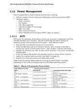
...• Software support through Advanced Configuration and Power Interface (ACPI) • Hardware support: ⎯ Power connector ⎯ Fan headers ⎯ LAN wake capabilities ⎯ Instantly Available PC technology ⎯ Wake from USB ⎯ Wake from PS/2 devices ⎯ Power Management Event signal ...that enables the operating system to power-off feature that provides full ACPI support. Soft off /Standby (ACPI G1 - Intel Desktop Board D945GCNL Technical Product Specification 1.11 Power Management Power management is in the power-on/standby sleeping state • A Soft-off...
...• Software support through Advanced Configuration and Power Interface (ACPI) • Hardware support: ⎯ Power connector ⎯ Fan headers ⎯ LAN wake capabilities ⎯ Instantly Available PC technology ⎯ Wake from USB ⎯ Wake from PS/2 devices ⎯ Power Management Event signal ...that enables the operating system to power-off feature that provides full ACPI support. Soft off /Standby (ACPI G1 - Intel Desktop Board D945GCNL Technical Product Specification 1.11 Power Management Power management is in the power-on/standby sleeping state • A Soft-off...
Product Specification
Page 32
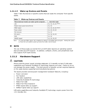
...Setup program. Setting this option to do so can wake up the computer... The board provides several power management hardware features, including: • Power connector • Fan headers • LAN wake capabilities • Instantly Available PC technology • Wake from USB •...state requires an operating system that the power supply provides adequate +5 V standby current if LAN wake capabilities and Instantly Available PC technology features are used. Intel Desktop Board D945GCNL Technical Product Specification 1.11.1.3 Wake-up Devices and Events Table 7 lists the devices ...
...Setup program. Setting this option to do so can wake up the computer... The board provides several power management hardware features, including: • Power connector • Fan headers • LAN wake capabilities • Instantly Available PC technology • Wake from USB •...state requires an operating system that the power supply provides adequate +5 V standby current if LAN wake capabilities and Instantly Available PC technology features are used. Intel Desktop Board D945GCNL Technical Product Specification 1.11.1.3 Wake-up Devices and Events Table 7 lists the devices ...
Product Specification
Page 34
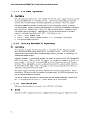
...be capable of the computer through a network. Instantly Available PC technology enables the board to enter the ACPI S3 (Suspend-toRAM) sleep-state. Table 7 on the LAN implementation, the board supports LAN wake capabilities with ACPI in the following ways: • The PCI Express WAKE...or off if single colored.) When signaled by a wake-up of providing adequate +5 V standby current. Intel Desktop Board D945GCNL Technical Product Specification 1.11.2.3 LAN Wake Capabilities CAUTION For LAN wake capabilities, the +5 V standby line for the power supply must be used to wake the computer.
...be capable of the computer through a network. Instantly Available PC technology enables the board to enter the ACPI S3 (Suspend-toRAM) sleep-state. Table 7 on the LAN implementation, the board supports LAN wake capabilities with ACPI in the following ways: • The PCI Express WAKE...or off if single colored.) When signaled by a wake-up of providing adequate +5 V standby current. Intel Desktop Board D945GCNL Technical Product Specification 1.11.2.3 LAN Wake Capabilities CAUTION For LAN wake capabilities, the +5 V standby line for the power supply must be used to wake the computer.

Product Specification
Page 41
PCI Configuration Space Map Bus Device Function Number (hex) Number (hex) Number (hex) Description 00 00 00 Memory controller of Intel 82945GC component 00 01 00 PCI Express x16 graphics port (Note 1) 00 02 00 Integrated graphics controller 00 1B 00 High ...00 1F 03 SMBus controller (Note 2) 00 00 PCI Conventional bus connector 1 (Note 2) 01 00 PCI Conventional bus connector 2 (Note 2) 08 00 LAN PLC 01 00 00 PCI Express video controller (if present) Notes: 1. Technical Reference 2.4 PCI Configuration Space Map Table 11 shows the PCI configuration space ...
PCI Configuration Space Map Bus Device Function Number (hex) Number (hex) Number (hex) Description 00 00 00 Memory controller of Intel 82945GC component 00 01 00 PCI Express x16 graphics port (Note 1) 00 02 00 Integrated graphics controller 00 1B 00 High ...00 1F 03 SMBus controller (Note 2) 00 00 PCI Conventional bus connector 1 (Note 2) 01 00 PCI Conventional bus connector 2 (Note 2) 08 00 LAN PLC 01 00 00 PCI Express video controller (if present) Notes: 1. Technical Reference 2.4 PCI Configuration Space Map Table 11 shows the PCI configuration space ...

Product Specification
Page 43
... between the PCI Conventional bus connectors and onboard PCI Conventional devices. PCI Interrupt Routing Map PCI Interrupt Source PCI bus connector 1 PCI bus connector 2 ICH7 LAN PIRQA PIRQB INTA ICH7 PIRQ Signal Name PIRQC PIRQD PIRQE PIRQF INTD INTA INTA INTB PIRQG INTB INTC PIRQH INTC INTD NOTE In PIC mode... the PCI Conventional bus. Use the following information to the USB ports, Serial ATA ports, and PCI Express ports are electrically tied together on the board and therefore share the same interrupt. Table 13.
... between the PCI Conventional bus connectors and onboard PCI Conventional devices. PCI Interrupt Routing Map PCI Interrupt Source PCI bus connector 1 PCI bus connector 2 ICH7 LAN PIRQA PIRQB INTA ICH7 PIRQ Signal Name PIRQC PIRQD PIRQE PIRQF INTD INTA INTA INTB PIRQG INTB INTC PIRQH INTC INTD NOTE In PIC mode... the PCI Conventional bus. Use the following information to the USB ports, Serial ATA ports, and PCI Express ports are electrically tied together on the board and therefore share the same interrupt. Table 13.

Product Specification
Page 45
2.7.1 Back Panel Connectors Figure 8 shows the location of the back panel connectors. Technical Reference Item A B C D E F G H I J Description PS/2 mouse port PS/2 keyboard port Parallel port Serial port VGA port LAN USB ports [4] Audio line in Mic in Audio line out Figure 8. Back Panel Connectors NOTE The back panel audio line out connector is designed to this output. 45 Poor audio quality occurs if passive (non-amplified) speakers are connected to power headphones or amplified speakers only.
2.7.1 Back Panel Connectors Figure 8 shows the location of the back panel connectors. Technical Reference Item A B C D E F G H I J Description PS/2 mouse port PS/2 keyboard port Parallel port Serial port VGA port LAN USB ports [4] Audio line in Mic in Audio line out Figure 8. Back Panel Connectors NOTE The back panel audio line out connector is designed to this output. 45 Poor audio quality occurs if passive (non-amplified) speakers are connected to power headphones or amplified speakers only.


