
Product Guide
Page 5
Contents 1 Desktop Board Features Desktop Board Components 10 Processor ...12 Main Memory...12 Intel® 945GC Express Chipset 13 S-Video Support 13 Onboard Audio Subsystem 13 Input/Output (I/O) Controller 14 LAN Subsystem 15 LAN Subsystem Software 15 LAN Status LEDs 15 Hi-Speed ... Precautions 22 Prevent Power Supply Overload 22 Observe Safety and Regulatory Requirements 22 Installing the I/O Shield 23 Installing and Removing the Desktop Board 24 Installing and Removing Memory 25 Installing DIMMs 25 Removing DIMMs 27 Connecting the IDE Cable 27 Connecting the Serial ATA (SATA...
Contents 1 Desktop Board Features Desktop Board Components 10 Processor ...12 Main Memory...12 Intel® 945GC Express Chipset 13 S-Video Support 13 Onboard Audio Subsystem 13 Input/Output (I/O) Controller 14 LAN Subsystem 15 LAN Subsystem Software 15 LAN Status LEDs 15 Hi-Speed ... Precautions 22 Prevent Power Supply Overload 22 Observe Safety and Regulatory Requirements 22 Installing the I/O Shield 23 Installing and Removing the Desktop Board 24 Installing and Removing Memory 25 Installing DIMMs 25 Removing DIMMs 27 Connecting the IDE Cable 27 Connecting the Serial ATA (SATA...
Product Guide
Page 7
... 33 13. Installing a DIMM 26 9. Location of the Standby Power Indicator 19 5. Intel Desktop Board D945GCLF2 China RoHS Material Self Declaration Table.........54 Tables 1. Intel Desktop Board D945GCLF2 Components 11 3. LAN Status LEDs 15 4. Safety Standards 47 13. EMC Regulations 55 ... 9 2. S/PDIF Connector Signal Names 31 6. Intel Desktop Board D945GCLF2 Mounting Screw Holes 24 7. Front Panel Audio Header Signal Names for the BIOS Setup Program Modes 36 9. Internal Headers 30 12. Intel Desktop Board D945GCLF2 Components 10 2. BIOS Configuration Jumper Block 35 15...
... 33 13. Installing a DIMM 26 9. Location of the Standby Power Indicator 19 5. Intel Desktop Board D945GCLF2 China RoHS Material Self Declaration Table.........54 Tables 1. Intel Desktop Board D945GCLF2 Components 11 3. LAN Status LEDs 15 4. Safety Standards 47 13. EMC Regulations 55 ... 9 2. S/PDIF Connector Signal Names 31 6. Intel Desktop Board D945GCLF2 Mounting Screw Holes 24 7. Front Panel Audio Header Signal Names for the BIOS Setup Program Modes 36 9. Internal Headers 30 12. Intel Desktop Board D945GCLF2 Components 10 2. BIOS Configuration Jumper Block 35 15...

Product Guide
Page 9
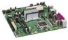
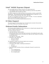
... 2 GB of system memory Intel® 945GC Express Chipset consisting of Intel® Desktop Board D945GCLF2. Feature Summary Form Factor Processor Main Memory Chipset Graphics Audio Expansion Capabilities Peripheral Interfaces BIOS LAN Support Power Management Supported Operating Systems Mini-ITX (171.45 millimeters [6.75 inches] x 171.45 millimeters [6.75 inches]) Dual-Core Intel® Atom™ processor • One 240...
... 2 GB of system memory Intel® 945GC Express Chipset consisting of Intel® Desktop Board D945GCLF2. Feature Summary Form Factor Processor Main Memory Chipset Graphics Audio Expansion Capabilities Peripheral Interfaces BIOS LAN Support Power Management Supported Operating Systems Mini-ITX (171.45 millimeters [6.75 inches] x 171.45 millimeters [6.75 inches]) Dual-Core Intel® Atom™ processor • One 240...
Product Guide
Page 13
...; GMA 950). Desktop Board Features Intel® 945GC Express Chipset The Intel 945GC Express Chipset consists of the following headers and connectors: • Onboard S/PDIF connector (3-pin) • Front panel audio header, including functionality for the board's I /O Controller Hub (ICH7) The GMCH component provides interfaces to the processor, memory, and the DMI interconnect. Onboard Audio Subsystem Intel Desktop Board D945GCLF2 has a 6-channel...
...; GMA 950). Desktop Board Features Intel® 945GC Express Chipset The Intel 945GC Express Chipset consists of the following headers and connectors: • Onboard S/PDIF connector (3-pin) • Front panel audio header, including functionality for the board's I /O Controller Hub (ICH7) The GMCH component provides interfaces to the processor, memory, and the DMI interconnect. Onboard Audio Subsystem Intel Desktop Board D945GCLF2 has a 6-channel...
Product Guide
Page 14
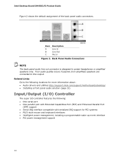
...amplified) speakers are connected to the following locations for more information about: • Audio drivers and utilities http://support.intel.com/support/motherboards/desktop/ • Installing a front panel audio solution (page 31) Input/Output (I/O) Controller The super I/O controller features the following... Description Line In Line Out Mic In Figure 2. Back Panel Audio Connectors NOTE The back panel audio line out connector is designed to power headphones or amplified speakers only. Intel Desktop Board D945GCLF2 Product Guide Figure 2 shows the default assignment of the back ...
...amplified) speakers are connected to the following locations for more information about: • Audio drivers and utilities http://support.intel.com/support/motherboards/desktop/ • Installing a front panel audio solution (page 31) Input/Output (I/O) Controller The super I/O controller features the following... Description Line In Line Out Mic In Figure 2. Back Panel Audio Connectors NOTE The back panel audio line out connector is designed to power headphones or amplified speakers only. Intel Desktop Board D945GCLF2 Product Guide Figure 2 shows the default assignment of the back ...

Product Guide
Page 21
... the SATA cable • Connect internal headers • Connect chassis fan and power supply cables • Set the BIOS configuration and audio jumpers • Clear passwords • Replace the battery Before You Begin CAUTIONS The procedures in this chapter assume familiarity with the general ...networks, or modems before you open the computer or perform any of the computer chassis. 21 Follow these guidelines before you begin installing the Desktop Board: • Always follow the steps in each procedure in the correct order. • Set up a log to disconnect power, telecommunications ...
... the SATA cable • Connect internal headers • Connect chassis fan and power supply cables • Set the BIOS configuration and audio jumpers • Clear passwords • Replace the battery Before You Begin CAUTIONS The procedures in this chapter assume familiarity with the general ...networks, or modems before you open the computer or perform any of the computer chassis. 21 Follow these guidelines before you begin installing the Desktop Board: • Always follow the steps in each procedure in the correct order. • Set up a log to disconnect power, telecommunications ...

Product Guide
Page 30
Item A B C D Description Audio S/PDIF Front panel Hi-speed USB 2.0 Figure 11. Internal Headers 30 Figure 11 shows the location of the board's internal headers. Intel Desktop Board D945GCLF2 Product Guide Connecting Internal Headers Before connecting cables to the internal headers, observe the precautions in "Before You Begin" on page 21.
Item A B C D Description Audio S/PDIF Front panel Hi-speed USB 2.0 Figure 11. Internal Headers 30 Figure 11 shows the location of the board's internal headers. Intel Desktop Board D945GCLF2 Product Guide Connecting Internal Headers Before connecting cables to the internal headers, observe the precautions in "Before You Begin" on page 21.

Product Guide
Page 31
...Begin" on page 21. 2. Turn off the computer and disconnect the AC power cord. 3. Install a correctly keyed and shielded front panel audio cable. Table 5. Table 4. Connecting the S/PDIF Connector Before connecting to the S/PDIF connector, observe the precautions in "Before You Begin" ... 31 Table 4 shows the pin assignments for the location of the front panel audio header. See Figure 11, B on page 30 for the front panel audio header. Installing and Replacing Desktop Board Components Connecting the Front Panel Audio Header Figure 11, A shows the location of the front panel header.
...Begin" on page 21. 2. Turn off the computer and disconnect the AC power cord. 3. Install a correctly keyed and shielded front panel audio cable. Table 5. Table 4. Connecting the S/PDIF Connector Before connecting to the S/PDIF connector, observe the precautions in "Before You Begin" ... 31 Table 4 shows the pin assignments for the location of the front panel audio header. See Figure 11, B on page 30 for the front panel audio header. Installing and Replacing Desktop Board Components Connecting the Front Panel Audio Header Figure 11, A shows the location of the front panel header.


