
Product Guide
Page 5
Contents 1 Desktop Board Features Desktop Board Components 10 Processor ...12 Main Memory...12 Intel® 945GC Express Chipset 13 S-Video Support 13 Onboard Audio Subsystem 13 Input/Output (I/O) Controller 14 LAN Subsystem 15 LAN Subsystem Software 15...Begin 21 Installation Precautions 22 Prevent Power Supply Overload 22 Observe Safety and Regulatory Requirements 22 Installing the I/O Shield 23 Installing and Removing the Desktop Board 24 Installing and Removing Memory 25 Installing DIMMs 25 Removing DIMMs 27 Connecting the IDE Cable 27 Connecting the Serial ATA (SATA) Cable ...
Contents 1 Desktop Board Features Desktop Board Components 10 Processor ...12 Main Memory...12 Intel® 945GC Express Chipset 13 S-Video Support 13 Onboard Audio Subsystem 13 Input/Output (I/O) Controller 14 LAN Subsystem 15 LAN Subsystem Software 15...Begin 21 Installation Precautions 22 Prevent Power Supply Overload 22 Observe Safety and Regulatory Requirements 22 Installing the I/O Shield 23 Installing and Removing the Desktop Board 24 Installing and Removing Memory 25 Installing DIMMs 25 Removing DIMMs 27 Connecting the IDE Cable 27 Connecting the Serial ATA (SATA) Cable ...
Product Guide
Page 7
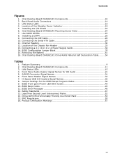
... Environmentally Friendly Use Period Mark 53 15. Back Panel Audio Connectors 14 3. Connecting a 2 x 10 or 2 x 12 Power Supply Cable 34 14. Intel Desktop Board D945GCLF2 Mounting Screw Holes 24 7. Connecting the Serial ATA Cable 29 11. Internal Headers 30 12. Front... Certification Markings 57 vii Installing a DIMM 26 9. Location of the Standby Power Indicator 19 5. Intel Desktop Board D945GCLF2 China RoHS Material Self Declaration Table.........54 Tables 1. BIOS Error Messages 46 12. Intel Desktop Board D945GCLF2 Components 10 2. Removing the Battery 41 16.
... Environmentally Friendly Use Period Mark 53 15. Back Panel Audio Connectors 14 3. Connecting a 2 x 10 or 2 x 12 Power Supply Cable 34 14. Intel Desktop Board D945GCLF2 Mounting Screw Holes 24 7. Connecting the Serial ATA Cable 29 11. Internal Headers 30 12. Front... Certification Markings 57 vii Installing a DIMM 26 9. Location of the Standby Power Indicator 19 5. Intel Desktop Board D945GCLF2 China RoHS Material Self Declaration Table.........54 Tables 1. BIOS Error Messages 46 12. Intel Desktop Board D945GCLF2 Components 10 2. Removing the Battery 41 16.

Product Guide
Page 9
....45 millimeters [6.75 inches]) Dual-Core Intel® Atom™ processor • One 240-pin SDRAM Dual Inline Memory Module (DIMM) socket • 667/533 MHz single channel DDR2 SDRAM interface • Supports up to 2 GB of system memory Intel® 945GC Express Chipset consisting of Intel® Desktop Board D945GCLF2. 1 Desktop Board Features This chapter briefly describes the main...
....45 millimeters [6.75 inches]) Dual-Core Intel® Atom™ processor • One 240-pin SDRAM Dual Inline Memory Module (DIMM) socket • 667/533 MHz single channel DDR2 SDRAM interface • Supports up to 2 GB of system memory Intel® 945GC Express Chipset consisting of Intel® Desktop Board D945GCLF2. 1 Desktop Board Features This chapter briefly describes the main...

Product Guide
Page 10
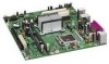
Figure 1. Intel Desktop Board D945GCLF2 Components 10 Intel Desktop Board D945GCLF2 Product Guide Desktop Board Components Figure 1 shows the location of the major components on Intel Desktop Board D945GCLF2.
Figure 1. Intel Desktop Board D945GCLF2 Components 10 Intel Desktop Board D945GCLF2 Product Guide Desktop Board Components Figure 1 shows the location of the major components on Intel Desktop Board D945GCLF2.

Product Guide
Page 15
...MAC address LAN Subsystem Software For LAN software and drivers, refer to the Intel Desktop D945GCLF2 link on the back panel (see Figure 3). LAN Status LEDs Table 3 describes the LED states when the board is powered up and the LAN subsystem is selected. 15 LAN Status LEDs...10 Mbits/s data rate is selected. 100 Mbits/s data rate is selected. 1000 Mbits/s data rate is operating. These LEDs indicate the operating states of the LAN. LAN Status LEDs Two LEDs are built into the RJ-45 LAN connector located on Intel's World Wide Web site at http://support.intel.com/support/motherboards/desktop...
...MAC address LAN Subsystem Software For LAN software and drivers, refer to the Intel Desktop D945GCLF2 link on the back panel (see Figure 3). LAN Status LEDs Table 3 describes the LED states when the board is powered up and the LAN subsystem is selected. 15 LAN Status LEDs...10 Mbits/s data rate is selected. 100 Mbits/s data rate is selected. 1000 Mbits/s data rate is operating. These LEDs indicate the operating states of the LAN. LAN Status LEDs Two LEDs are built into the RJ-45 LAN connector located on Intel's World Wide Web site at http://support.intel.com/support/motherboards/desktop...

Product Guide
Page 29
Attach the cable end without the lock to the desktop board. Connecting the Serial ATA Cable 29 Attach the locking cable end to the connector on page 21. 2. Figure 10. Observe the precautions in "Before You Begin" on the board (Figure 10, A). 3. Installing and Replacing Desktop Board Components Connecting the Serial ATA (SATA) Cable The SATA cable supports the Serial ATA protocol and connects a single drive to the drive (Figure 10, B). For correct cable function: 1.
Attach the cable end without the lock to the desktop board. Connecting the Serial ATA Cable 29 Attach the locking cable end to the connector on page 21. 2. Figure 10. Observe the precautions in "Before You Begin" on the board (Figure 10, A). 3. Installing and Replacing Desktop Board Components Connecting the Serial ATA (SATA) Cable The SATA cable supports the Serial ATA protocol and connects a single drive to the drive (Figure 10, B). For correct cable function: 1.

Product Guide
Page 31
..., observe the precautions in "Before You Begin" on page 21. 2. See Figure 11, B on page 21. Installing and Replacing Desktop Board Components Connecting the Front Panel Audio Header Figure 11, A shows the location of the front panel header. Table 4. Table 5 shows ... 1 PORT 1L 3 PORT 1R 5 PORT 2R 7 SENSE_SEND 9 PORT 2L Pin Signal Name 2 GND 4 PRESENCE# 6 SENSE1_RETURN 8 KEY (no pin) 10 SENSE2_RETURN To install a cable that connects a front panel audio solution to the computer. Table 5. S/PDIF Connector Signal Names Pin Signal Name 1 VCC 2 ...
..., observe the precautions in "Before You Begin" on page 21. 2. See Figure 11, B on page 21. Installing and Replacing Desktop Board Components Connecting the Front Panel Audio Header Figure 11, A shows the location of the front panel header. Table 4. Table 5 shows ... 1 PORT 1L 3 PORT 1R 5 PORT 2R 7 SENSE_SEND 9 PORT 2L Pin Signal Name 2 GND 4 PRESENCE# 6 SENSE1_RETURN 8 KEY (no pin) 10 SENSE2_RETURN To install a cable that connects a front panel audio solution to the computer. Table 5. S/PDIF Connector Signal Names Pin Signal Name 1 VCC 2 ...

Product Guide
Page 32
...Names USB Port A USB Port B Pin Signal Name 1 Power 3 D- 5 D+ 7 Ground 9 Key Pin Signal Name 2 Power 4 D- 6 D+ 8 Ground 10 No connect Note: USB ports may be assigned as needed. 32 Front Panel Header Signal Names Pin Signal In/Out Description Pin Signal In/Out...the location of the front panel header. Table 7. Table 6. Table 7 shows the pin assignments for the front panel header. Intel Desktop Board D945GCLF2 Product Guide Connecting to the Front Panel Header Before connecting to the USB 2.0 headers, observe the precautions in "Before You Begin" on...
...Names USB Port A USB Port B Pin Signal Name 1 Power 3 D- 5 D+ 7 Ground 9 Key Pin Signal Name 2 Power 4 D- 6 D+ 8 Ground 10 No connect Note: USB ports may be assigned as needed. 32 Front Panel Header Signal Names Pin Signal In/Out Description Pin Signal In/Out...the location of the front panel header. Table 7. Table 6. Table 7 shows the pin assignments for the front panel header. Intel Desktop Board D945GCLF2 Product Guide Connecting to the Front Panel Header Before connecting to the USB 2.0 headers, observe the precautions in "Before You Begin" on...

Product Guide
Page 34
... power supply cable (2 x 10 or 2 x 12) to the 2 x 2 connector (Figure 13). 3. Intel Desktop Board D945GCLF2 Product Guide Connecting Power Supply Cables CAUTION Failure to use an appropriate power supply and/or not connecting the 12 V (2 x 2) power connector to the Desktop Board may result in "Before You Begin" on page 21. 2. Connect the 12 V processor core voltage power supply...
... power supply cable (2 x 10 or 2 x 12) to the 2 x 2 connector (Figure 13). 3. Intel Desktop Board D945GCLF2 Product Guide Connecting Power Supply Cables CAUTION Failure to use an appropriate power supply and/or not connecting the 12 V (2 x 2) power connector to the Desktop Board may result in "Before You Begin" on page 21. 2. Connect the 12 V processor core voltage power supply...

Product Guide
Page 36
...Setup. 10. Disconnect the computer's power cord from the AC power source (wall outlet or power adapter). 3. Recovery (None) The BIOS recovers data from a recovery diskette in "Before You Begin" on pins 2-3 as shown below. 6. Observe the precautions in the event of the Desktop Board's BIOS... Configure (2-3) After the Power-On Self-Test (POST) runs, the BIOS displays the Maintenance Menu. Use this menu to boot. 7. Intel Desktop Board D945GCLF2 Product Guide Figure 14 shows the location of a failed BIOS update. Replace the cover, plug in the computer and the configuration jumper is ...
...Setup. 10. Disconnect the computer's power cord from the AC power source (wall outlet or power adapter). 3. Recovery (None) The BIOS recovers data from a recovery diskette in "Before You Begin" on pins 2-3 as shown below. 6. Observe the precautions in the event of the Desktop Board's BIOS... Configure (2-3) After the Power-On Self-Test (POST) runs, the BIOS displays the Maintenance Menu. Use this menu to boot. 7. Intel Desktop Board D945GCLF2 Product Guide Figure 14 shows the location of a failed BIOS update. Replace the cover, plug in the computer and the configuration jumper is ...

Product Guide
Page 45
...beep codes can be heard through a speaker attached to display messages. BIOS Front-panel Power LED Blink Codes Type Processor initialization complete POST complete BIOS update in Table 10. repeat entire pattern (three on-off blinks and 3-second pause) until system is powered off Memory error On-off...when system powers up, then off for 0.5 second On when system powers up, then off for 0.5 second when processor initialization is used by the BIOS to the board's line out jack (see Table 9). BIOS Beep Codes Type Pattern Memory error Three long beeps Thermal warning Four alternating...
...beep codes can be heard through a speaker attached to display messages. BIOS Front-panel Power LED Blink Codes Type Processor initialization complete POST complete BIOS update in Table 10. repeat entire pattern (three on-off blinks and 3-second pause) until system is powered off Memory error On-off...when system powers up, then off for 0.5 second On when system powers up, then off for 0.5 second when processor initialization is used by the BIOS to the board's line out jack (see Table 9). BIOS Beep Codes Type Pattern Memory error Three long beeps Thermal warning Four alternating...

Product Guide
Page 53
...Pollution by electronic information products (EIP). The official title of the China RoHS regulation is "Management Methods for Intel Desktop Board D945GCLF2 is defined as EU RoHS. The EFUP for cadmium, which listed controlled substances will not leak or chemically ... Polybrominated diphenyl ether (PBDE) The maximum concentrations allowed are 0.1% or 1000 ppm (except for Intel Desktop Boards has been determined to be 10 years. Table 14. Intel Desktop Board D945GCLF2 is an example of the symbol used by industry generally to describe legislation implemented by the Ministry ...
...Pollution by electronic information products (EIP). The official title of the China RoHS regulation is "Management Methods for Intel Desktop Board D945GCLF2 is defined as EU RoHS. The EFUP for cadmium, which listed controlled substances will not leak or chemically ... Polybrominated diphenyl ether (PBDE) The maximum concentrations allowed are 0.1% or 1000 ppm (except for Intel Desktop Boards has been determined to be 10 years. Table 14. Intel Desktop Board D945GCLF2 is an example of the symbol used by industry generally to describe legislation implemented by the Ministry ...
